A normal differential-pressure reading does not guarantee that your dust collection system has adequate airflow. Differential pressure primarily tells you the resistance across the filters. Poor airflow can still result from fan performance, duct restrictions, closed dampers, system imbalance, air leaks, process modifications, or even an inaccurate DP reading. CFM needs to be measured independently.
Sometimes we receive a call from one of our customers because dust isn’t being captured at the hoods. We ask about differential pressure and hear: “DP looks great. We’re only running around 3 inches.” That’s useful information, but now we need to know how much air is actually moving through the system.
How Can DP Be Normal When CFM Is Low?
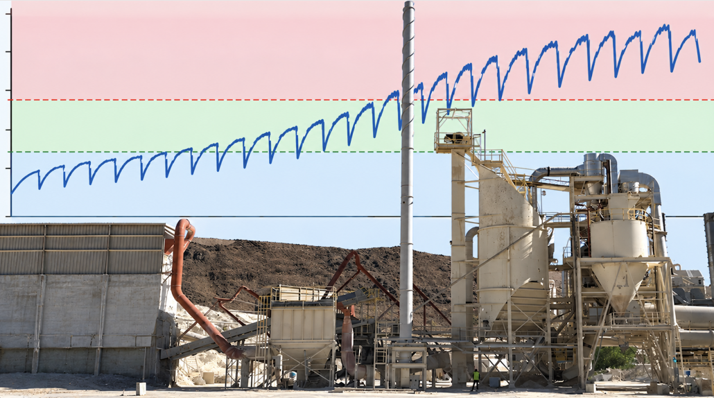
DP across the collector tells us how much resistance the air encounters as it passes through the filters. In general, loaded filters create more resistance.
But imagine that the fan is moving substantially less air than it should. Less air passing through the filters can also produce a relatively low pressure drop. So a reading that looks like “clean filters” may actually coexist with insufficient system airflow.
“What's your differential pressure?” is one of the first questions I ask. But if the complaint is poor pickup, I also want airflow measurements. You can't diagnose the entire system from the DP gauge.”
When DP appears reasonable but capture is poor, we would investigate several areas:
Could the Fan Be the Problem?
Yes, and this is where static-pressure measurements become valuable. A fan doesn’t simply “make 20,000 CFM.” It produces airflow according to the resistance of the system and its fan curve.
If the system resistance has increased because of duct modifications, buildup, new equipment, additional fittings, or other restrictions, the fan operating point can shift, and actual CFM can fall. Check fan RPM, rotation, belts or coupling, VFD frequency, motor current, inlet/outlet conditions, and actual static pressure.
This graphic shows how a dust collector fan’s airflow changes as the resistance in the system changes. The most important point is where the black Static Pressure curve and the blue System Resistance curve cross. That intersection is the fan’s actual operating point. In this example, the fan is operating at about 60,000 ACFM and 9 in. w.g. of static pressure.
The four curves show different things:
⦿ Black – Static Pressure: How much pressure the fan can produce at different airflow rates. As airflow increases beyond a certain point, the fan’s available static pressure decreases.
⦿ Blue – System Resistance: How much resistance the dust collection system creates at different airflow rates. As you try to move more air through ducts, filters, hoods, elbows, and other components, resistance increases rapidly.
⦿ Green – Shaft Power: Approximately how much power the fan requires at each airflow. At the operating point shown, it is around 120 HP.
⦿ Orange – Static Efficiency: How efficiently the fan is operating. At the operating point, the graph indicates an efficiency of roughly 70%.
A fan does not automatically deliver its rated CFM. Its actual airflow depends on the resistance of the entire dust collection system.
Could the Ductwork Be Restricting Airflow?
We have inspected systems where the collector received most of the attention while the real problem was several hundred feet upstream.
Look for dust accumulation, crushed or damaged duct, partially closed dampers, sharp transitions, poor branch entries, excessive flexible duct, and modifications made since the original system was balanced.
Adding branches is especially important. Changing one branch can affect airflow in the others, and adding new dust sources to an existing system can reduce air volume and duct velocity in the original branches.
What Should I Measure?
If you’re troubleshooting this condition, get three pieces of information together:
Collector DP + actual airflow + system static pressure.
Then compare them with the system’s original design or commissioning data.
For example, suppose a system was designed for 20,000 CFM at 10 in. w.g. total static pressure. Today the collector DP is a comfortable 3 in. w.g., but field testing shows only 14,500 CFM. Changing the filters because the pickup is poor probably isn’t where we’d start. We’d find out why 5,500 CFM is missing.
Make Sure the DP Reading Is Real
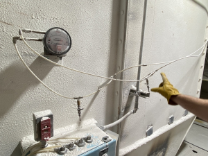
Plugged sensing lines can produce misleading readings.
Finally, verify the instrument. Plugged sensing lines, moisture, disconnected tubing, reversed high/low connections, a bad gauge, or incorrect transmitter/PLC scaling can all produce misleading readings.
If the number doesn’t make sense compared with what you’re seeing in the plant, verify it with a known-good differential-pressure instrument before making maintenance decisions. We usually recommend to have a good spare differential pressure gauge for this purpose.
If your DP looks normal but the dust isn’t being captured, Baghouse.com can measure the actual airflow and pressures throughout the system and help identify where the performance is being lost.
1. Does low differential pressure mean my filters are good?
Not necessarily. Low DP means there is relatively low measured resistance between the dirty and clean sides of the collector, but the airflow through the filters also affects that reading.
If the fan is moving substantially less air than it should, filter differential pressure may look comfortably low even though the system isn’t capturing enough dust. That’s why we like to evaluate DP together with actual CFM rather than using DP alone to judge filter condition.
2. Can clogged ductwork cause low CFM without high collector DP?
Yes. Collector DP measures pressure loss across the collector at its sensing locations, so a major restriction upstream in the duct network may reduce the amount of air that ever reaches the collector.
Dust buildup, a partially closed damper, damaged duct, or a restricted branch can therefore produce poor airflow at a hood while collector DP remains fairly normal. Static-pressure measurements at several points in the duct system can help locate where the restriction occurs.
3. Can adding pickup points reduce airflow at existing hoods?
Yes. If the fan cannot provide the additional CFM required by the new pickup points, the available airflow will be redistributed through the duct network.
Existing hoods, particularly those on more restrictive or distant branches, may lose capture velocity. This is why adding another machine to a dust collection system should include an airflow review rather than simply cutting a new connection into the existing main duct.
4. Should I replace filters if DP is normal but suction is poor?
Usually, we would investigate the airflow problem before ordering filters. Check actual CFM, fan RPM and rotation, VFD frequency, system static pressure, dampers, duct restrictions, and recent system modifications. Also verify that the DP gauge and sensing lines are working correctly. If the filters are physically damaged, blinded, contaminated, or otherwise failing, replacement may still be appropriate, but poor suction by itself doesn’t prove that the filters are responsible.
5. How do I know if the fan is producing enough CFM?
Measure actual airflow and static pressure while the system is operating under normal production conditions, then compare those measurements with the fan curve and original design requirements.
Also verify fan RPM, rotation, motor current, belt condition, VFD frequency, and inlet/outlet conditions. If a fan designed to deliver 20,000 CFM is currently moving only 14,500 CFM, the next step is to determine why its operating point has changed rather than assuming the collector needs more filter area.
6. Can a VFD cause low airflow?
Yes. Fan speed has a major effect on airflow. If a VFD was installed, reprogrammed, placed in manual mode, or limited to a lower maximum frequency, the fan may be operating below its intended RPM. During troubleshooting, check the actual VFD output frequency and fan RPM rather than assuming that 100% on the operator display represents the original design speed.
7. What if the DP gauge never changes?
A DP reading that stays almost perfectly fixed through different production or cleaning conditions deserves investigation. Check the dirty- and clean-side pressure taps for blockage, inspect the sensing tubing for dust, moisture, kinks, leaks, or disconnections, and verify that the high and low connections are installed correctly.
For electronic transmitters, also check zero, range, wiring, and PLC scaling. Comparing the installed instrument against a known-good handheld differential-pressure gauge or manometer is one of the quickest ways to determine whether the reading can be trusted.
President | Dust Collection Engineer | Industrial Air Pollution Control Specialist
Matt Coughlin is an author, engineer, and dust collection expert specializing in industrial filtration systems, air pollution control, and process ventilation. With more than two decades of experience in the dust collection industry, Matt has helped design, troubleshoot, and optimize hundreds of dust collection systems across a wide range of industries, including cement, mining, food processing, woodworking, metals, power generation, chemical manufacturing, and bulk material handling. Born and raised in Southern California, Matt continues to work closely with industrial facilities around the world, helping companies improve their dust collection performance through engineering expertise, practical solutions, and long-term technical support.