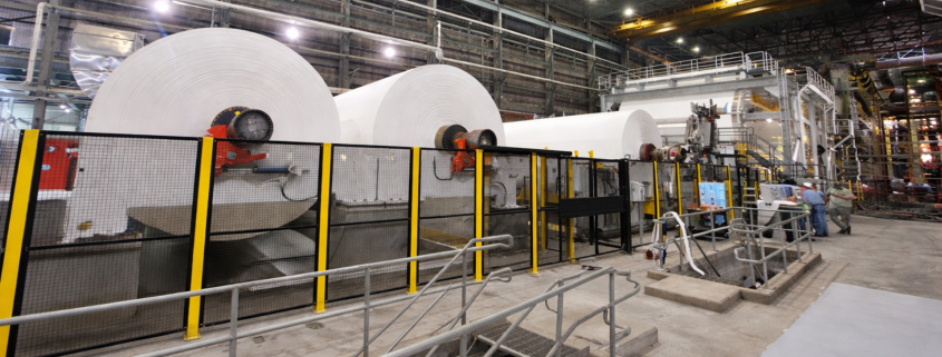
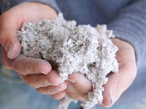
In paper mills, cutting, slitting, die-cutting, rewinding, conveying, baling, and finishing all generate fine particles that disperse quickly if capture velocities drop even slightly.

Dust collection in packaging plants and paper mills is often treated as a housekeeping issue, when in reality it is a core process system that directly affects safety, uptime, and product quality. Paperboard trim, corrugated scrap, tissue dust, additives like calcium carbonate, and even plastic or metal fines all behave differently, but they share one critical trait: when they become airborne, they are difficult to control and dangerous to ignore. Facilities that succeed in this environment are the ones that design dust collection around how dust actually behaves, not how it looks on a spec sheet.

Why Dust in Packaging and Paper Mills Behaves Differently

Cellulose Fibers DustPaper and packaging dust is deceptively light. Cellulose fibers, tissue dust, and cardboard fines don’t fall out of the air the way heavier industrial dusts do. They stay suspended, migrate through buildings, and settle in places operators rarely inspect until there is already a problem. Cutting, slitting, die-cutting, rewinding, conveying, baling, and finishing all generate fine particles that disperse quickly if capture velocities drop even slightly.

This is where many systems fall short. Capture hoods are often undersized, duct velocities are marginal, and airflow assumptions are based on rules of thumb that do not account for fibrous dust behavior. As Matt Coughlin, owner of Baghouse.com, often puts it, “Paper dust doesn’t give you a warning. If the airflow isn’t right, it just leaves. By the time you see it on the floor, it’s already been in the air all shift.” Effective dust collection in these facilities starts at the source, with consistent airflow and duct design that keeps material moving instead of settling.

Where Dust Collection Systems Commonly Break Down in Paper and Packaging Plants

Most pulp, paper and packaging facilities technically have dust collection, but were never designed to handle continuous production dust loads. We routinely see systems that were installed to “keep things clean” rather than to capture dust at the rate it is actually generated. Over time, ductwork fills with fibrous buildup, elbows become choke points, and airflow quietly degrades.

Another common issue is the cleaning strategy. Timer-based pulsing is still widely used, even though paper dust loading fluctuates constantly throughout a shift. This leads to filters being over-cleaned when they don’t need it and under-cleaned when they do. Differential pressure gauges are often ignored, damaged, or inaccurate, which removes one of the most valuable diagnostic tools operators have. 

Why Baghouse Collectors Make Sense for Paper and Packaging Dust

Baghouse system for paper mill facility

Baghouse collectors tolerate high dust loading without losing performance

Baghouse collectors are particularly well-suited for paperboard, cardboard, tissue, and packaging dust because they tolerate high dust loading without losing stability. Unlike cartridge collectors, which can blind quickly in fibrous applications, baghouses allow dust cake to form and release more predictably when cleaned correctly. This stability is critical in operations where airflow must remain consistent to protect cutting quality, trim removal, and material handling.

When equipped with proper cages, wear protection, and differential-pressure-controlled cleaning, baghouse systems maintain lower and more stable pressure drop, extend filter life, and reduce compressed air consumption. They also scale well for large air volumes common in converting and corrugating operations. In facilities handling mixed dust streams (paper fibers, mineral additives, and occasional plastic fines), a baghouse offers flexibility that simpler systems cannot.

Combustible Dust Protection Should Be Part of the System, Not an Add-on

Standard for Combustible Dusts and Particulate Solids (2025)

Standard for Combustible Dusts and Particulate Solids (2025)

Paper and cardboard dust are classified as combustible by OSHA and NFPA, which means dust collection systems must be designed with explosion risk in mind. A dust collector is an enclosed vessel filled with suspended fuel; without proper protection, it can become the most dangerous piece of equipment in the building.

Explosion venting, isolation devices, backdraft dampers, and proper grounding are not optional features in these environments. They are integral components of a safe system, especially when filtered air is returned to the workspace. History has shown that ignoring this reality leads to catastrophic consequences. As Matt Coughlin notes, “Dust collection reduces risk everywhere else in the plant, but only if the collector itself is designed to fail safely.”

Questions & Answers: Practical Dust Collection Guidance for Packaging and Paper Mills

Why is paper and cardboard dust considered so dangerous?
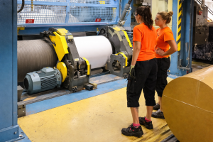
Personnel at paper millPaper and cardboard dust are dangerous because they combine three problems at once: they are respirable, combustible, and highly mobile. When suspended in air, even relatively low concentrations can ignite if an ignition source is present. When allowed to settle, the dust accumulates rapidly on horizontal surfaces, creating fuel for secondary explosions. From a health standpoint, prolonged exposure also contributes to poor indoor air quality and respiratory issues, particularly in tissue and fine-paper operations.

Do paper mills and packaging facilities really need a dust hazard analysis (DHA)?

If combustible dust is present, yes. NFPA 660 requires facilities that generate, handle, or store combustible dust to perform and document a dust hazard analysis. This is not just a paperwork exercise. A properly executed DHA identifies where dust is generated, how it moves through the facility, where it can accumulate, and what ignition sources exist. Facilities that skip this step often end up addressing problems reactively after an incident or inspection.

What makes paper dust harder to capture than heavier industrial dust?
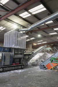
Adding additional PVC curtain strips to the shredder dust extraction capture hood serves two purposes; firstly to help contain any airborne dust particles within this enclosure and secondary to enable manual loading of the shredder hopper.

Adding additional PVC curtain strips to the shredder dust extraction capture hood serves two purposes; firstly to help contain any airborne dust particles within this enclosure and secondary to enable manual loading of the shredder hopper.

Paper dust has low bulk density and a fibrous structure that allows it to stay airborne longer and cling to duct walls. This means capture velocities must be maintained consistently, duct transitions must be smooth, and dead zones must be avoided. Small losses in airflow that might go unnoticed in other industries quickly show up as visible dust in paper operations.

Are cyclones enough for paper and cardboard dust?

Cyclones are effective for removing larger trim and scrap before the air reaches the collector, and they can significantly reduce filter loading. However, they are not sufficient on their own. Fine paper dust requires high-efficiency filtration downstream, which is where a baghouse becomes essential. The most reliable systems use cyclones as a first stage and baghouses for final filtration.

Why do filters seem to plug so quickly in paper applications?

Plugging is usually a symptom, not the root problem. Common causes include unstable airflow, incorrect cleaning strategy, damaged or reused cages that restrict bag movement, and inaccurate differential pressure readings. When cleaning is controlled by actual pressure drop instead of a timer, filter performance and life improve dramatically.

How often should baghouse filters be replaced in paper mills?

There is no universal replacement interval. Filters should be changed based on performance trends, not calendar dates. When differential pressure no longer stabilizes after cleaning, or when emissions increase despite proper operation, it is time to investigate. Accurate monitoring is key; without it, filters are often replaced too early or far too late.

factory equipment inside industrial conveyor line transporting packageCan dust collection really reduce downtime in packaging plants?

Yes, and often in ways operators don’t immediately connect to dust. Stable airflow improves trim removal, reduces jams in balers and conveyors, lowers housekeeping labor, and protects sensitive equipment. Facilities with well-designed dust collection systems spend less time reacting and more time producing.

How does Baghouse.com support paper and packaging facilities?

Baghouse.com approaches these applications by designing systems around real dust behavior and production demands, not generic airflow tables. That includes proper hood design, duct layout that resists buildup, baghouse selection matched to dust characteristics, explosion protection integrated from the start, and ongoing support to keep systems performing as conditions change.

The goal is not just compliance, but long-term operational stability.

Staggering the pulse sequence changes that dynamic. By separating recently cleaned rows from those that are still loaded, the dust cake forms more uniformly.

Pulse-jet dust collectors have a reputation for being simple, almost set-it-and-forget-it pieces of equipment. And its true… when they work well, they quietly protect your process, your people, and your permit. But when they do not, they let you know through rising differential pressure, short filter life, unstable airflow, and the constant sense that you are reacting instead of operating.

The first thing to understand is that pulse-jet cleaning does not just remove dust. Every pulse rearranges the dust cake that remains on the filter, and that dust cake is doing most of the real filtration work. In systems with high upward gas velocities, especially those handling fine or light dust, submicron particles can separate from the rest of the dust stream. Over time, they form a very dense layer on the bag surface. That layer increases airflow resistance and drives up differential pressure, even when the filters look visually clean.

If you are fighting high-pressure drop and frequent pulsing, this behavior is often the real culprit.

Why pulse sequence matters

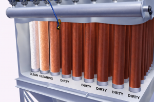
pulse jet cleaning sequence

Typical pulse-jet row cleaning sequence.

One of the most common setup mistakes is pulsing filter rows in simple numerical order. It feels logical, but it can actually work against you. When rows are cleaned one after another, fine material can migrate toward the rows that were just pulsed. The dust cake never has a chance to stabilize, and the system ends up cleaning more often than necessary.

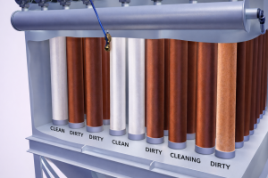
Staggering the pulse sequence changes that dynamic.

pulse jet cleaning sequence

Recommended pulse-jet row cleaning sequence.

By separating recently cleaned rows from those that are still loaded, the dust cake forms more uniformly. Filtration improves, pressure drop becomes more predictable, and cleaning frequency often drops. In many cases, filter life improves as well, without changing filters, valves, or fans.

Getting pulse timing and frequency under control

Pulse duration is another area where small adjustments make a big difference. For standard high-pressure, low-volume pulse-jet collectors, pulses should be short and crisp. The goal is to create a shock wave inside the bag, not to inflate it for as long as possible. In most applications, a pulse duration between 0.10 and 0.15 seconds is effective, assuming it aligns with the filter and valve manufacturer’s recommendations.

Cleaning frequency deserves just as much attention. Pulse too often and you destroy the dust cake you are trying to maintain. Pulse too slowly and differential pressure climbs until airflow and capture suffer. In real-world systems, pulse intervals can range from one second to 30 seconds or more. The most reliable control variable is differential pressure across the collector. Many pulse-jet systems operate best with an average pressure drop in the range of 3 to 6 inches of water column, depending on the filter media and process conditions.

Clean-on-demand control and compressed air

Clean on-demand systems help stabilize all of this. 

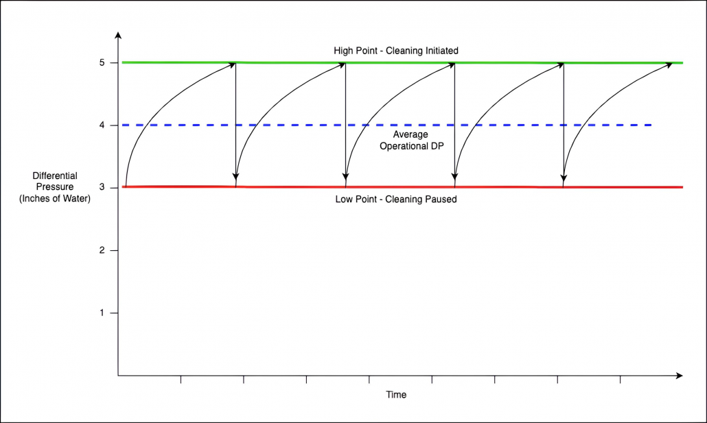
Graphic showing the inches of water column. HIGH Point - Cleaning Initiated" and at the bottom "Low - Cleaning Paused". The line going through the middle is "Average operational DP".

In a clean-on-demand mode, the cleaning system will activate once the collector differential pressure rises to the set HIGH point and will continue cleaning until enough dust cake has been removed to drop the differential pressure to the set LOW point.

Using a differential pressure switch, such as a Photohelic gauge, allows the collector to clean only when needed. The system begins pulsing at the high pressure set point and stops when it cleans down to the low set point. Keeping those set points within about 0.5 to 1.0 inch of water column of each other reduces compressed air usage and prevents unnecessary cleaning.

Just as important, pulse frequency should never exceed the recovery capability of the compressed air system. Each pulse should fire only after header pressure has fully recovered so that every row is cleaned with the same force. Header recharge time depends on compressor capacity and the size of the feed line to the header tank. In many installations, a 1.5-inch feed line is typical, but undersized piping can quietly undermine pulse effectiveness.

When pulse-jet problems are mechanical, not settings-related

Not all pulse-jet problems are control-related. Pulse valves themselves are frequent troublemakers. Diaphragm failure, dirt, oil, or moisture entering the valve body can all reduce cleaning energy. Disassembling and inspecting valves is often the fastest way to confirm the issue. Before doing that, it is worth checking that tubing and fittings between the pulse valves and solenoid valves are intact, leak-free, and correctly connected.

The electrical side matters too. Timer boards and solenoid pilot valves should be verified before deeper mechanical work begins. A control fault can look exactly like a compressed air problem if you are not careful.

Can velocity and why light dust is unforgiving

Can velocity is the vertical gas velocity throughout the housing, above the hopper level but before reaching the bottom of the bags.

Can velocity is the vertical gas velocity throughout the housing, above the hopper level but before reaching the bottom of the bags.

Pulse-jet collectors typically clean online and often have inlets below the filters. In these designs, can velocity becomes critical, especially when handling light-density dust at or below 35 lb/ft³. Excessive can velocity, often above 250 to 300 feet per minute depending on the dust, can drive high pressure drops and persistent re-entrainment.

Increasing available filter area is one way to address this. Pleated filters provide more surface area than traditional bags, allowing fewer elements and more open airflow area. That directly reduces can velocity. In some cases, relocating the inlet above the bottom of the filters can also reduce turbulence and re-entrainment.

The quiet damage caused by cages and poor fit

Bent or damaged cages cannot properly support the bag, leading to uneven flexing and premature failure. In corrosive environments, rust and pitting abrade the fabric during every cleaning cycle. Even sharp edges on cage bottom pans can cause long-term damage that only shows up once bags begin to fail.


Installation details that prevent repeat failures

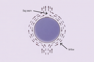
filter bag seams

In pulse-jet collectors, all bag seams should face the same direction.

Proper installation plays a major role in filter life. Bag seams should all face the same direction. This simple practice provides a consistent reference point when diagnosing failures. If bags consistently fail opposite the seam, inlet abrasion is often the underlying cause. Without that reference, patterns are easy to miss.

Bag-to-cage fit is just as critical. Filters that are too loose or too tight limit collection efficiency and shorten service life. Allowing the correct amount of excess fabric, often referred to as the pinch, depends on the fabric type and must be matched to the cage dimensions.

Bag and cage damage inspection guide

Five fundamentals that define pulse-jet collectors performance

Even when pulse settings are dialed in and filters are installed correctly, many baghouses struggle because of basic design and operating choices made years earlier.

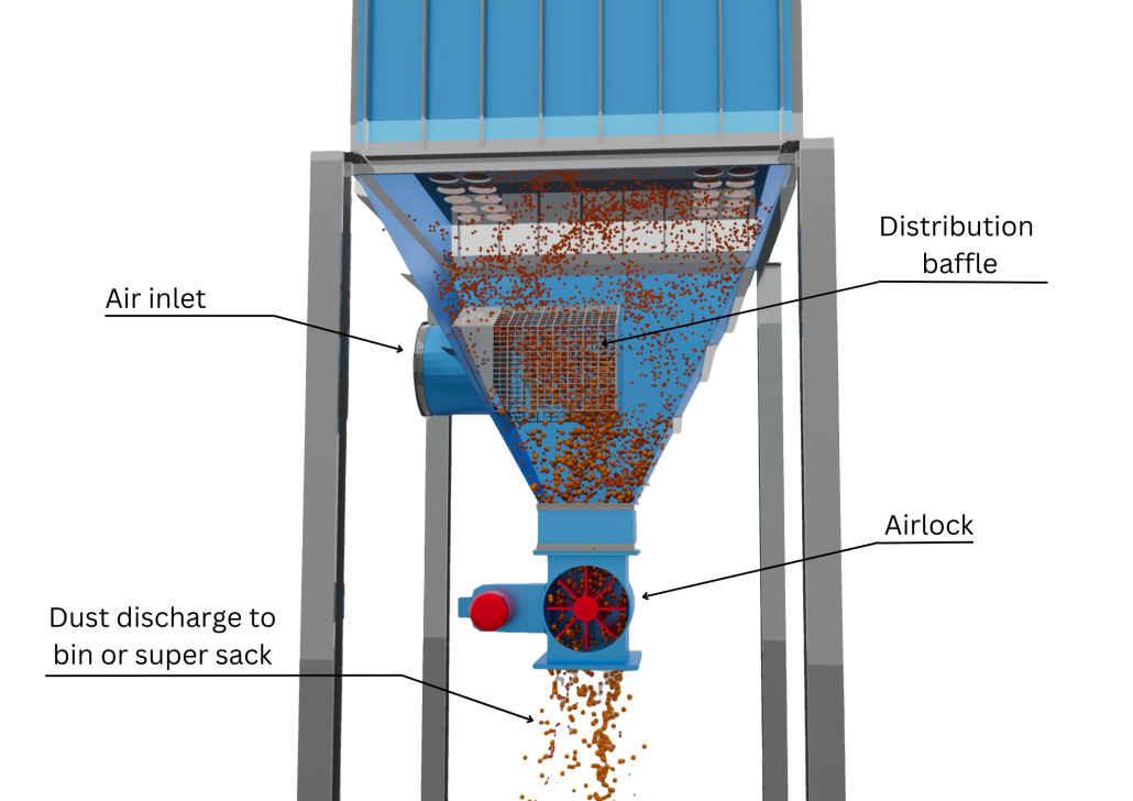
1 – Use an inlet design that is right for your application. Graphic showing the air inlet to the baghouse, the distribution baffle, the dust bin or super sack and the rotary airlock.Dust-laden air often enters through a dirty-air inlet located in the hopper below the filters. If that inlet directs airflow downward or creates excessive turbulence, dust can swirl upward and become re-entrained on the bags. The result is higher grain loading than the filters can handle efficiently. Enlarging the inlet to reduce velocity or installing a ladder vane baffle inside the hopper can dramatically improve airflow distribution. These baffles are typically inexpensive and easy to install, yet they reduce turbulence, minimize re-entrainment, and protect the filters from uneven loading and abrasion.
Using pleated filters is often the most effective way to bring an overloaded system back into balance.

2 – Improve the air-to-cloth ratio. It defines how much air is handled per unit of filter area, and when it is too aggressive, problems follow quickly. High pressure drop, poor cleaning, and weak capture at pickup points are common symptoms. 

Pulse-jet collectors can operate at higher air-to-cloth ratios than shaker or reverse-air units, but there are still practical limits.In many ambient temperature pulse-jet applications, ratios above about 6 to 1 push the system toward instability. High-temperature systems usually need to be more conservative. Increasing filter area, including the use of pleated filters, is often the most effective way to bring an overloaded system back into balance.

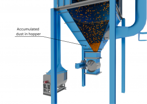
3 – Don’t use the hopper for material storage. They are designed to allow dust-laden air to enter the collector and to discharge collected material continuously. 

Dust accumulated in hopper, airlock and fan.

When a hopper is used for material storage, dust can build up and re-enter the airstream, abrading the lower portions of the filters and shortening their life. Even without intentional storage, dust buildup on hopper walls or bridging over the outlet can cause re-entrainment or sudden slugs of material. Continuous dust removal using an airlock or dump valve helps keep the system stable.

4 – Make sure that baghouse access doors seal properly. Poorly sealed doors allow air leakage, dust leakage, heat loss, and condensation. That condensation can lead to filter failure and severe corrosion. Door seals are inexpensive compared to the problems they prevent, but they need regular inspection. Ensuring positive contact between the seal and the door panel goes a long way toward maintaining consistent operation.

Maintenance Checklist Main Image5 – Conduct proper maintenance and recordkeeping. This often determine whether a baghouse improves over time or slowly deteriorates. Tracking pressure drop, grain loading, inlet temperature, cleaning adjustments, and emission levels provides the information needed to spot trends early. Recording conditions during startup, shutdown, filter inspections, and troubleshooting builds a baseline that makes future decisions clearer and faster. Good records also support compliance and reduce the risk of unexpected failures.

Stability is rarely accidental

A pulse-jet collector that runs well is usually the result of thoughtful pulse settings, sound mechanical condition, good airflow design, and attention to operational details that are easy to overlook until they start causing trouble. When those fundamentals are in place, the system stops demanding attention and starts doing what it was meant to do, quietly and reliably.

And if you suspect your collector could do better, there are often more opportunities hiding in plain sight. A short conversation with experienced baghouse specialists can uncover practical adjustments and design improvements that are specific to your process, not just textbook recommendations.

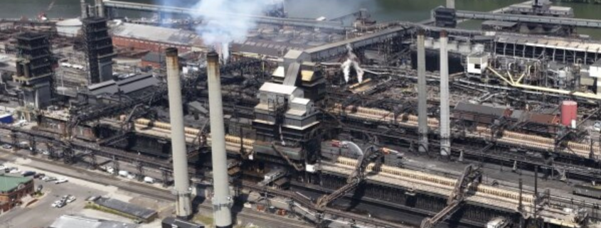
Clairton Coke Works

Clairton Coke Works fined $118K for safety lapses

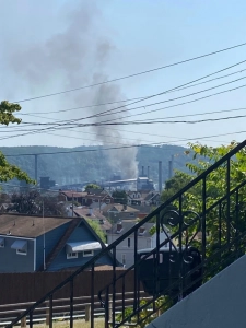
This image provided by Amy Sowers shows smoke from the Clairton Coke Works, Monday, Aug. 11, 2025 in Clairton, Pa. (Amy Sowers via AP)

This image provided by Amy Sowers shows smoke from the Clairton Coke Works, Monday, Aug. 11, 2025 in Clairton, Pa. (Amy Sowers via AP)

The deadly explosion at Clairton Coke Works is a sobering reminder of what can happen when combustible hazards are not fully understood, anticipated, or controlled. On August 11, an explosion tore through an area between Batteries 13 and 14 at the plant, killing two workers and injuring at least ten others. Witnesses described the blast as powerful enough to shake nearby buildings and send thick black smoke into the sky. “It felt like thunder,” said a construction worker near the scene. “Shook the scaffold, shook my chest, and shook the building… and it’s like something bad happened.”

Following the incident, Occupational Safety and Health Administration issued 10 citations and $118,000 in fines against the company, pointing to inadequate safety procedures, insufficient employee training, and failures to properly isolate equipment from hazardous energy sources. OSHA also cited a contractor on site for similar deficiencies. Investigators determined that the explosion was caused by a valve rupturing while workers were washing it with water, releasing highly combustible coke oven gas into a confined space. Once released, the gas ignited, triggering a devastating blast—an explanation that aligns with early findings from the U.S. Chemical Safety Board.

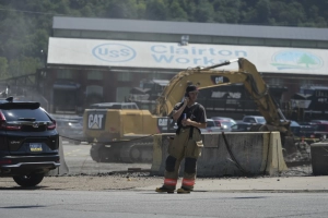
An emergency crew is seen after an explosion at the Clairton Coke Works, a coking plant, Monday, Aug 11, 2025, in Clairton, Penn. (AP Photo/Gene Puskar)

An emergency crew is seen after an explosion at the Clairton Coke Works, a coking plant, Monday, Aug 11, 2025, in Clairton, Penn. (AP Photo/Gene Puskar)

Union leaders and community members were blunt about the human cost. United Steelworkers District 10 Director Bernie Hall stated, “We are grateful to OSHA for thoroughly investigating the tragic incident that cost two lives and impacted many others.” A local resident, reflecting on the plant’s history of explosions, asked, “How many more lives are going to have to be lost until something happens?” These statements underscore a painful reality: enforcement actions, fines, and investigations almost always come after lives are lost, not before.

While this specific incident involved coke oven gas, the underlying risk dynamics closely mirror those seen in combustible dust events. Fuel, an ignition source, and confinement (whether it’s gas in a battery area or dust inside a duct, silo, or collector) can escalate rapidly into a fireball or explosion. Facilities that generate combustible dust face similar exposure when hazards are underestimated, processes change, or protection systems lag behind production demands.

This is why preparedness matters. If your dust is combustible, having the right equipment in place—spark detection, abort gates, isolation valves, explosion venting or suppression, and properly designed dust collection systems—is not optional. It is a core part of protecting workers and maintaining operational continuity. Just as important is involving experts who understand how combustible dust behaves in real-world systems and how standards apply in practice.

Companies like Baghouse.com help bridge that gap by supporting facilities through testing, Dust Hazard Analyses, system design, and the selection of certified fire and explosion protection equipment. Combustible dust compliance is not a checkbox exercise; it requires experience, system-level thinking, and proactive planning. The Clairton explosion stands as a stark reminder that waiting until after an incident to address combustible hazards is too late. Preparedness, expert guidance, and the right protection strategies can prevent today’s risks from becoming tomorrow’s tragedy.

What Is the Difference Between Leak Testing and Broken Filter Detectors?

If you’ve ever walked with a plant manager and maintenance personnel taking care of a dust collection system and heard someone say, “We already have leak detectors, so we’re covered,” there’s a good chance two very different concepts are being mixed together.

Leak testing and broken filter detectors both deal with emissions and filter integrity, but they answer very different questions, operate on very different timelines, and serve different roles in a dust collection program. Confusing them can lead to missed failures, false confidence, or unnecessary downtime.

Let’s break down what each one actually does, when it should be used, and how they work together in real plants.

Leak Testing: A Snapshot in Time

Leak testing is a manual, periodic verification method. It’s designed to answer one specific question: Is the collector leaking RIGHT NOW?

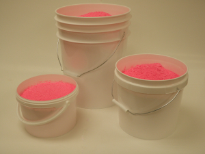
Green and Pink Leak Testing Powder

The benefits of leak testing far outweigh the risks associated with system failures.

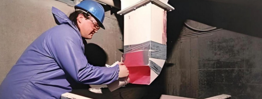
Most commonly, leak testing involves introducing a fluorescent powder or tracer into the inlet of the dust collector while it’s operating. The clean air plenum, tubesheet, doors, seams, and other potential leak points are then inspected using UV light to see where powder is getting through.

Dominick Dal Santo, Dust Collection Expert at Baghouse.com, puts it plainly: “Leak testing is one of the best tools we have to confirm installation quality and sealing integrity, but it’s a moment-in-time test. It tells you what’s happening TODAY, not what’s going to happen next week.”

This makes leak testing extremely valuable during:

  • ✔️ Commissioning of a new collector
  • ✔️ Startup after a filter changeout or major maintenance
  • ✔️ Troubleshooting visible emissions or indoor dust complaints
  • ✔️ Verifying NFPA or environmental compliance after modifications

However, once the test is over, the system goes back to normal operation, and anything that fails after that point goes unnoticed until the next inspection.

Real Life Leak Testing Scenario

Dusting in the clean air plenum

Dusting in the clean air plenum

A cement plant replaces all filter bags during a planned outage. Everything looks good visually, but during startup they notice some dusting in the clean air plenum. A leak test reveals several minor leaks at door gaskets and a handful of bags that were pinched during installation.

The issues are corrected immediately, avoiding a compliance problem and saving the plant from weeks of chasing unexplained dust. In this case, leak testing does exactly what it’s meant to do: confirm workmanship and sealing before the plant moves on.

But once production ramps up, bag failures caused by abrasion, chemical attack, or pulse cleaning stress won’t be caught by leak testing alone.

Broken Filter Detectors: Continuous Awareness

A entry level triboelectric broken bag detection system

A entry level triboelectric broken bag detection system

Broken filter detectors (often triboelectric or electrodynamic sensors) are continuous monitoring devices. Instead of asking “Is there a leak right now?”, they answer a different question: “Did something change?”

These sensors are installed in the clean air duct or stack and continuously measure particulate activity. When a filter tears, a bag drops, or a cartridge cracks, the particulate level changes… and the detector flags it.

Matt Coughlin, President of Baghouse.com, explains it this way: “A broken filter detector isn’t about absolute emissions. It’s about trend deviation. It tells you that the system isn’t behaving the way it did yesterday.”

That distinction matters. Broken filter detectors are excellent at catching:

  • ✔️ Sudden bag failures
  • ✔️ Progressive filter degradation
  • ✔️ Maintenance errors (like a bag left unseated)
  • ✔️ Early warning signs before visible emissions appear

They don’t replace leak testing, but they cover the gap between inspections.

Real-World Monitoring Scenario

A metal foundry facility runs a baghouse handling fine particulate with tight OSHA exposure limits. Everything passes leak testing during annual maintenance. Six months later, a single filter develops a tear near the snap band due to vibration of the compressed air pulse jet.

There’s no visible plume outside, and no one notices dust inside the plant….yet. But the broken filter detector shows a slow, consistent upward trend. Maintenance investigates, finds the failed bag, and replaces it during a short planned stop. Without continuous monitoring, that single failure could have gone unnoticed for months.

Where Plants Get It Wrong

Dominick notes: “We see facilities assume a tribo sensor means they’re compliant. In reality, it just tells you something changed. You still need testing, engineering judgment, and an understanding of your process.”

On the flip side, some plants rely only on annual or semi-annual leak testing and assume that’s sufficient. In high-risk applications (combustible dust, silica, or recirculated air), that’s often not enough.

Another challenge is poor sensor placement or configuration. A detector installed too close to a fan, elbow, or turbulent area can produce noisy data that operators eventually ignore. At that point, the sensor exists—but it’s not actually protecting anyone.

Leak Testing vs. Broken Filter Detection

In a nutshell, leak testing is diagnostic and confirmatory. It finds where dust is leaking and allows you to physically fix it.

Broken filter detectors are protective and preventative. They alert you when performance changes, often before people or regulators notice.

Matt summarizes it well: “If leak testing is your inspection report, broken filter detectors are your smoke alarm. You wouldn’t choose one instead of the other.”

Our Technical Recommendation

For most industrial dust collection systems (especially those tied to compliance, recirculation, or combustible dust risk) the best approach is layered.

leak detection powder bucketLeak testing should be used:

  • ✔️ After major maintenance
  • ✔️ During commissioning
  • ✔️ When troubleshooting known issues

Broken filter detectors should be used:

  • ✔️ On systems where downtime is costly
  • ✔️ Where indoor air quality limits are tight
  • ✔️ When early warning is more valuable than absolute measurement

And most importantly, both should be backed by people who understand how the system actually operates. Sensors don’t replace expertise. Tests don’t replace vigilance.

Leak testing and broken filter detectors aren’t competing tools. Plants that understand the difference build systems that are safer, more reliable, and easier to manage. If you’re unsure which approach—or combination—fits your operation, that’s usually a sign it’s time for a deeper look at the process, not just the equipment.

Here is where our expertise comes in handy!

Dust Collection Testing inspection

Most dust collection systems don’t fail overnight. They slowly drift away from their original design until one day emissions spike, operators start complaining, or the fan is pulling way more horsepower than it should. By then, you are reacting instead of managing.

Dust Collection Testing inspectionSystem-wide testing is how you catch those problems early. Done correctly, testing tells you whether your dust control system is still doing the job it was designed to do, and whether it can safely handle today’s production demands.
Why Testing Matters in the Real World

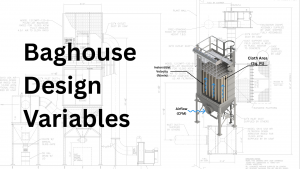
Designing a baghouse system requires careful calculation and optimization of multiple design variables to ensure reliable performance, regulatory compliance, and long-term durability.

Designing a baghouse system requires careful calculation and optimization of multiple design variables to ensure reliable performance, regulatory compliance, and long-term durability.

There are two core reasons to test a dust collection system. First, to confirm the system is operating as designed. Duct velocities, airflow at hoods, pressure drop across the collector, and fan performance all drift over time due to wear, buildup, and process changes. Second, to verify that the system is actually reducing airborne dust and employee exposure. A baghouse can be running, fans spinning, gauges moving, and still not be controlling dust effectively where it matters most. Testing connects airflow numbers to real exposure reduction.

What Does Testing Really Involve?

At its core, system testing is about airflow and pressure. Those two things tell you almost everything about how the system is behaving.

A proper test provides data to:

  • ✔️ Check performance against the original design
  • ✔️ Set and lock blast gates correctly
  • ✔️ Identify maintenance problems before they become outages
  • ✔️ Understand whether the system can handle additional pickup points
  • ✔️ Improve future system designs using real operating data

Start With the System, Not the Equipment

Before you touch a manometer or Pitot tube, gather the paperwork. If original drawings and calculations exist, use them. If not, sketch the system yourself. Document duct sizes, lengths, branch locations, fittings, hoods, dampers, and major components. This alone often reveals issues like undersized branches, unnecessary elbows, or field modifications that were never rebalanced. These drawings become your roadmap for where to measure and what results should look like.

Below, you will see a list of the items you will need to perform the inspection:

Evaluation Equipment

✔️ Paper, pencil, recording devices

✔️ Smoke tubes, candles

✔️ Velometer

✔️ Pilot tube, manometer, hoses

✔️ Drill, bits

✔️ Tape measure

✔️ Flashlight

✔️ Ladder

✔️ Rags

✔️ Watch

✔️ RPM meter

✔️ Sound level meter

✔️ Volt/amp meter

Previously Recorded Data

✔️ Original design specifications and drawings

✔️ Original operating conditions

✔️ Modifications

✔️ Past inspection reports

✔️ Persons to contact

✔️ Maintenance schedule

✔️ Controls

✔️ Lockout provisions

✔️ Compliance inspections

✔️ Exposure monitoring records

✔️ Injury and illness history

Employee contact

✔️ Complaints

✔️ Suggestions

✔️ Observed work practices

✔️ Interaction with control

✔️ Interaction with emission source

✔️ Training

✔️ Use of personal protective equipment (PPE)

✔️ Cooperation

Emission Source

✔️ Location of emissions

✔️ Rates of emission

✔️ Chemical characteristics

✔️ Physical characteristics

✔️ Employee exposure levels

✔️ Environment

Hood

✔️ Type (enclosure, receive, capture)

✔️ Capture velocity

✔️ Face velocity

✔️ Performance during normal operation

✔️ Performance during abnormal operation

✔️ Compatibility with work requirements

✔️ Physical integrity

✔️ competing air currents

✔️ Hood static pressure

✔️ Hood entry loss

Ductwork

✔️ Physical integrity

✔️ Plugging and blockage

✔️ Transport velocities

✔️ Duct material

✔️ Changes since last inspection

✔️ Blast gate and damper settings

Air Cleaner

✔️ Physical integrity

✔️ Static pressure drop

✔️ Waste stream handling

✔️ Maintenance and operation

✔️ PM program followed

Fan

✔️ Direction of rotation

✔️ RPM

✔️ Pulleys, belts

✔️ Access doors

✔️ Fan wheel

✔️ Fan housing

✔️ Flexible coupling

✔️ Inlet/outlet

✔️ Stack weather head

✔️ Bearings

✔️ Vibration and noise

✔️ Fan SP/fan TP

Fan Motor

✔️ RPM

✔️ Rated HP

✔️ Amperage

✔️ Actual BHP

✔️ Drive train

✔️ Temperature

✔️ Weather protection

✔️ Vibration

Replacement Air

✔️ Same CFM as exhaust

✔️ Force on doors

✔️ Drafts at exterior walls

✔️ Inlets

✔️ Heat/cooling source

✔️ Distribution

✔️ Interference with capture velocity

✔️ Back-up system

✔️ Monitoring or warning system

Measurement and Calculations

✔️ Hood static pressure

✔️ Capture velocity

✔️ Face velocities

✔️ Duct diameters, lengths

✔️ Duct transport velocities

✔️ Temperature, pressure

✔️ Flow rates

✔️ Fan SP/fan TP

✔️ Fan RPM

✔️ Motor RPM

✔️ Motor amps

✔️ System static pressure

Maintenance Checklist Image

Airflow Measurements

Baghouse variables such as airflow, air-to-cloth ratio, etc need to be considered when designing the system.Airflow inside a duct is never uniform. Measuring velocity at a single point gives you misleading data. Proper airflow measurement requires traversing the duct cross-section. Divide the duct into equal areas and measure velocity pressure at the center of each area. The smaller the areas, the more accurate the result.
Velocity is calculated using the relationship:

V = 4005 × √VP

Once you calculate individual velocities, average them, multiply by duct cross-sectional area, and you get airflow in cubic feet per minute.

For best results:

  • ✔️ Perform traverses at least eight duct diameters away from elbows, hoods, or branches
  • ✔️ Make two traverses at right angles whenever possible
  • ✔️ Correct for air density when temperature, moisture, or altitude differ significantly from standard conditions
  • ✔️ Expect dust loading to affect instrument performance and plan accordingly

Static Pressure

Static pressure readings are extremely sensitive to how measurement ports are installed. Static pressure taps should be flush with the inside duct wall, drilled rather than punched, and free of burrs. Poorly installed taps can create false readings that send you chasing problems that do not exist.

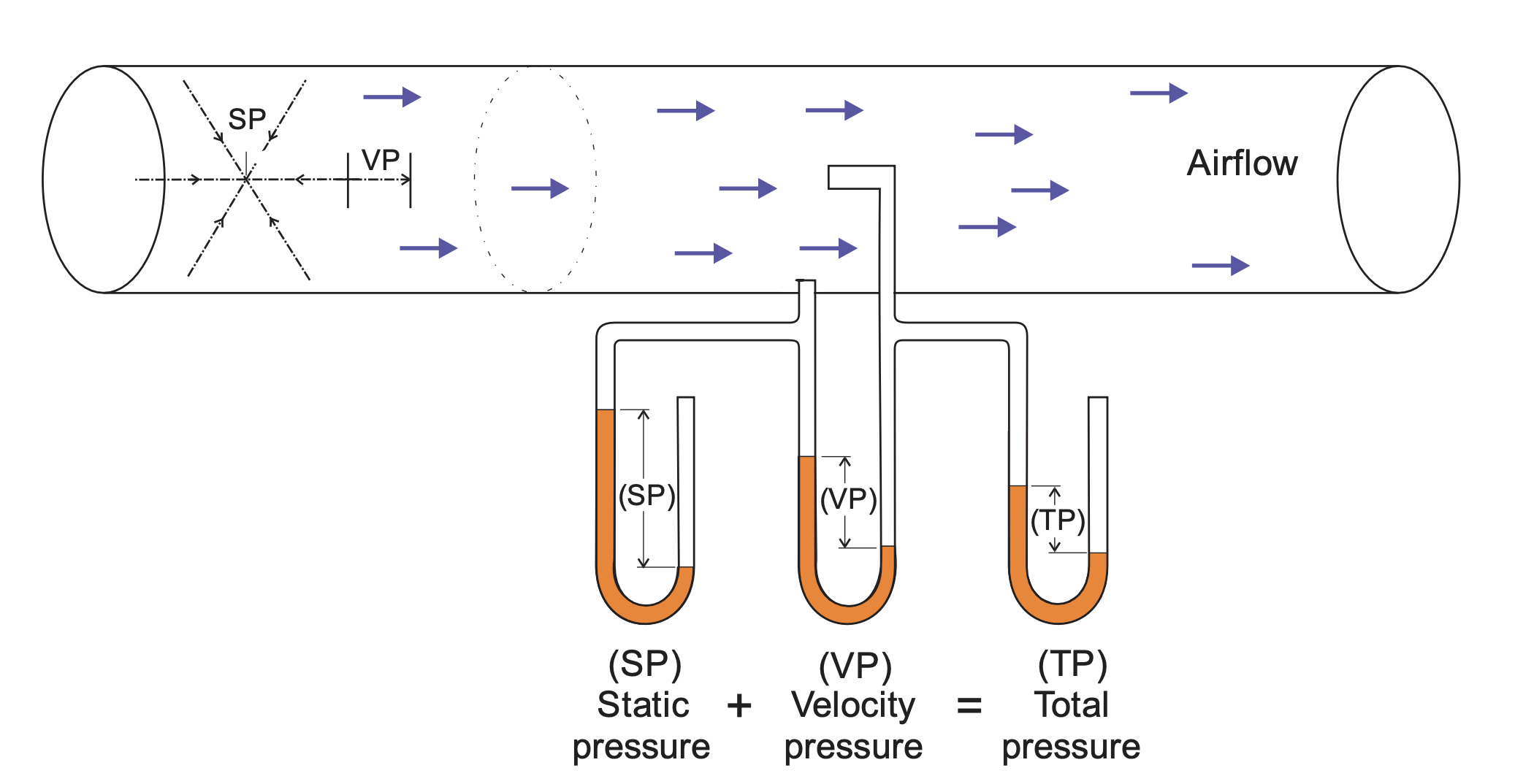
Relationship between static pressure, velocity pressure, and total pressure. Example represents the suction side of the fan.

Relationship between static pressure, velocity pressure, and
total pressure. Example represents the suction side of the fan.

Avoid measuring static pressure at elbows or locations with high turbulence. Sudden expansions or contractions in ductwork will distort readings. Static pressure data helps you understand where energy is being lost and whether pressure drops match design expectations.

Common Performance Problems and What They Usually Mean

When airflow drops, the cause is rarely mysterious.

Plugged ducts reduce volume immediately and usually point to insufficient transport velocity or buildup from moisture or sticky dusts. Fan issues often trace back to belt slippage, rotor wear, or material buildup inside the fan housing. Leaks in ductwork from loose doors, broken joints, or corrosion silently steal airflow and increase operating cost.

System changes matter. Adding exhaust points or adjusting blast gates without rebalancing almost always degrades performance elsewhere. Rising pressure drop across the collector usually signals cleaning system issues, blinded filters, or incorrect cleaning settings.

Evaluating Dust Control

Airflow alone does not tell you whether dust exposure is actually reduced. That requires sampling. Two types of samples are typically used. Process or source samples measure dust concentrations directly at or near the emission source or the worker most affected. Ambient or background samples measure dust levels away from the source but within the same environment, helping separate source emissions from overall plant dust.

Sampling Tools and What They Are Good For

Instantaneous dust monitors provide real-time feedback. They are excellent for identifying major dust sources and evaluating control effectiveness during operation changes.

Gravimetric samplers provide time-weighted average concentrations and material analysis. They are essential for exposure evaluation, but poor at identifying when and where dust spikes occur. The best evaluations use both.

Practical Sampling Approaches

Short-term system-on versus system-off testing shows immediate control effectiveness. Before-and-after testing demonstrates the impact of new controls. A-B-A testing compares two control methods under identical conditions, then returns to the original system to confirm changes were not process-related. This approach is especially useful when deciding between competing control strategies.

Turning Data Into Answers

Dust control effectiveness can be evaluated graphically to visualize differences, or mathematically to quantify efficiency.

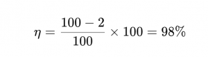
Efficiency is calculated as:

η = (Coff − Con) / Coff × 100%

What each term means

  • ➡️ η (eta) – Collection efficiency, expressed as a percentage

  • ➡️ Coff – Dust concentration before the collector (inlet concentration)

  • ➡️ Con – Dust concentration after the collector (outlet concentration)

Concentrations are usually measured in units like mg/m³, grains/ft³, or similar.

Simple example

If:

  • ✔️ Coff = 100 mg/m³

  • ✔️ Con = 2 mg/m³

Then:

collection efficiency formula

That means the dust collector is removing 98% of the particulate entering the system.

One important caveat

High efficiency doesn’t automatically mean safe recirculation or regulatory compliance. Even a 99.9% efficient system can still exceed OSHA limits if the inlet concentration is high or the dust is hazardous (silica, metals, combustible dust).

Repeated measurements at the same location should be treated statistically to account for variability. Recording operating conditions alongside measurements often explains results that would otherwise look inconsistent.

Baghouse Inspections: Catching Problems Before They Escalate

🔎 Daily Walk-Through and Maintenance

  • ✔️ Take pressure drop readings
  • ✔️ Check cleaning system 
performance (including 
compressors, dryer, filter)
  • ✔️ Check valve and damper 
operation
  • ✔️ Check dust removal system 
operation
  • ✔️ Check emission levels

🔎 Weekly Check-In and Maintenance

  • ✔️ Check diaphragm and solenoid operation
  • ✔️ Take differential pressure and Magnehelic 
line readings
  • ✔️ Check moving parts for wear/malfunction
  • ✔️ Take differential pressure (delta P) readings 
after a cleaning cycle (if increasing over time, indicates
bags becoming blinded)
  • ✔️ Check compartment interiors visually for leaks

🔎 Quarterly Inspection and Maintenance

  • ✔️ Remove sample bags for permeability flow testing
  • ✔️ Check fan operation
  • ✔️ Replace any failed bags
  • ✔️ Lubricate high wear parts
  • ✔️ Clean tubesheets

🔎 Annual Inspection and Maintenance

  • ✔️ Perform dye testing of each compartment to check for leaks
  • ✔️ Inspect access door gaskets
  • ✔️ Inspect ductwork and hopper baffles
  • ✔️ Adjust dampers or valves
  • ✔️ Calibrate instrumentation
dust collection system inspection

The Real Goal of System Testing

The point of testing is to understand how the system behaves today compared to how it was designed to behave. When testing and inspections are done together, operators gain control instead of reacting to failures. Energy use drops, emissions stabilize, bag life improves, and production interruptions become far less common.

A dust collection system that is measured, understood, and maintained will always outperform one that is simply left running and hoped for the best.