

Oil Mist Collector Sizing: How Much CFM Does Your CNC Machine Need?
Oil mist collector sizing starts with your machine’s enclosure size. For an enclosed CNC machine, multiply the enclosure’s open interior volume (in cubic feet) by 3 to 5 air changes per minute. That gives you the CFM needed to keep the enclosure under slight negative pressure, so mist gets pulled into the collector instead of rolling out the door. Then adjust for coolant pressure, door openings, and filter loading.
Below is the step-by-step method our engineers use, with three common examples and the mistakes we see most often in sizing.
Why Does CFM (Airflow) Matter?
An undersized mist collector with too little airflow will allow mist to escape every time the operator opens the door. It ends up on the floor, on the machine next to it, and in your people’s lungs.
However, too much airflow causes problems too. An oversized collector pulls large coolant droplets and even fine chips out of the work zone which wastes coolant, loads up the collector faster, and raises maintenance and energy costs unnecessarily. So the idea is to pull enough airflow to remove the mist, without pulling excess CFM which is inefficient.
The goal is the smallest airflow that holds the enclosure under negative pressure during the worst part of the cycle.
How to Size an Oil Mist Collector in 5 Steps
- Measure the enclosure’s interior. Measure the inside length, width, and height of the machine guarding in inches. Multiply them, then divide by 1,728 to get cubic feet.
- Subtract what’s inside. The table, spindle head, turret, and fixtures take up space. Subtract 15–20% for a typical machine, or more for a crowded one.
- Pick an air change rate. Use 3 to 5 air changes per minute for an enclosed machine:
- 3 per minute: standard flood coolant, long cycles, doors rarely opened.
- 4 per minute: typical CNC job-shop work.
- 5 per minute: high-pressure or through-spindle coolant, high spindle speeds, short cycles with frequent door openings, or visible smoke.
- Net volume (cubic feet) x air changes per minute = required CFM.
- Add 20–30% margin. This covers duct and hose losses, and some inefficiency for when the filters aren’t cleaned. Pick a collector whose rated airflow is at or above this number. For variable-speed units like the MistBuster, you then dial airflow down to what the machine actually needs.
Units check: some manufacturers quote air changes per hour, not per minute. 3–5 per minute equals 180–300 per hour. If you see a guide recommending “20 air changes” with no time unit, ask which one it means as the difference is significant.
 Example 1: CNC Turning Center
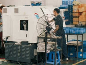
A compact CNC lathe has an enclosure measuring 60″ L x 36″ W x 48″ H.
- Volume: 60 x 36 x 48 = 103,680 cubic inches ÷ 1,728 = 60 cubic feet
- Minus 20% for the headstock, turret, and chuck: 48 cubic feet net
- Flood coolant, standard pressure: 3 air changes per minute
- 48 x 3 = 144 CFM
- Plus 25% margin: about 180 CFM
Collector: MistBuster 500, as the requirement is well below its 500 CFM maximum. There’s plenty of margin if you later add higher-pressure coolant.
 Example 2: Vertical Machining Center
 Example 2: Vertical Machining Center
A mid-size VMC enclosure measures 84″ L x 48″ W x 72″ H.
- Volume: 84 x 48 x 72 ÷ 1,728 = 168 cubic feet
- Minus 20%: 134 cubic feet net
- Typical job-shop work with regular door openings: 4 air changes per minute
- 134 x 4 = 536 CFM
- Plus 25%: about 670 CFM
Collector: this is above the MistBuster 500’s 500 CFM rating, so the right choice is a MistBuster 850. If the same shop ran flood coolant at 3 changes per minute, the requirement drops to about 400 CFM net (500 with margin), right at the 500’s limit. We would usually recommend the 850 to be on the safe side.
 Example 3: VMC with Through-Spindle Coolant
 Example 3: VMC with Through-Spindle Coolant
Take the same 134-cubic-foot VMC, now running 1,000 PSI through-spindle coolant.
- 134 cubic feet x 5 air changes per minute = 670 CFM
- Plus 25%: about 840 CFM
Collector: MistBuster 850. High-pressure coolant creates finer, denser mist, so this application also needs the 850’s second electronic cell, not just its higher airflow. That second cell is designed for coolant pressures from 600 to 1,500 PSI (AQE). If this machine is part of a bigger cell, or the enclosure is larger, the requirement can pass 850 CFM. At that point we’d look at a larger unit like a Smog Hog or a central system.
What if my Machine Isn’t Fully Enclosed?
The air-change method only works for enclosed machines. For open-front or partially guarded machines, size by the open area instead. Measure all openings in square feet and multiply by a capture velocity: 50 feet per minute for a vertical door opening, or about 75 feet per minute if the opening includes the roof.
Example: a 3 ft x 4 ft open door = 12 sq ft x 50 FPM = 600 CFM.
Open machines need much more airflow for the same capture. Enclosing the area using sheet-metal guarding or a door is often cheaper than buying a bigger collector.
Five Common Mistakes
- Sizing by horsepower or spindle size. Spindle power doesn’t tell you the enclosure volume, the coolant pressure, or how often the door opens. The enclosure volume is the most critical sizing factor.
- Ignoring coolant pressure. A machine upgraded to high-pressure coolant can need about 70% more airflow (going from 3 to 5 changes per minute) and a different collector.
- Forgetting the ductwork. Each foot of hose and each elbow adds resistance. Keep the connections short and smooth, or add more margin.
- Running the fan wide open. If your unit has variable airflow, set it to the calculated CFM, not the maximum, to run most efficiency.
- Putting the inlet in the splash zone. Mount the collector inlet high in the enclosure and away from direct coolant spray and chips. Otherwise you’ll collect liquid coolant and chips.
Should I Use a Central Collector or One Small Collector Per Machine?
For one to three machines, a machine-mounted unit on each is usually simplest. There’s no long ductwork, each machine can run independently, and you can add collectors one at a time. For larger groups, a central system sized for the machines that run at the same time can cost less per machine. We size those as engineered systems, and they require some engineering review to account for ductwork and hood design and static pressure losses. Contact us to help you spec out a central mist collection system.
Get a free sizing check
Send us your machine make and model, the enclosure dimensions, the coolant type and pressure, and a photo of the machine. A Baghouse.com engineer will run the numbers and recommend a collector, usually within one business day.

President | Dust Collection Engineer | Industrial Air Pollution Control Specialist
Matt Coughlin is an engineer, and dust collection expert specializing in industrial filtration systems, air pollution control, and process ventilation. Matt has helped design, troubleshoot, and optimize hundreds of dust collection systems across a wide range of industries, including cement, mining, food processing, woodworking, metals, power generation, chemical manufacturing, and bulk material handling. Born and raised in Southern California, Matt continues to work closely with industrial facilities around the world, helping companies improve their dust collection performance through engineering expertise, practical solutions, and long-term technical support.
