What is a Dust Explosion and How Does It Begin?

Combustible dusts present both fire and explosion risks. What technologies can help you prevent them?

What is Combustible Dust?

Many manufacturing processes create very small particles of dust that settle on surfaces throughout the plant. Eventually these particles not only create a housekeeping issue, but if the particles are combustible, they can represent a potential fire or explosion hazard. Combustible dusts generally present both fire and explosion risks so it may help to consider the management of these risks separately.

Fire triangle and explosion pentagon

Fire triangle

Fire management strategies traditionally focus on the control or elimination of one of the three key elements necessary for a fire — often represented by the “fire triangle.”

Explosion Pentagon

The explosion pentagon includes two additional elements necessary for an explosion: dispersion of a “Dust Cloud” and “Confinement” of dust. The management or removal of one or more of the elements in the explosion pentagon can reduce the explosion risk. 

What is a Dust Explosion and How Does It Begin?

A dust explosion can be defined as: Any solid material that can burn in air will do so with a violence and speed that increases, with increasing degree of subdivision of the material. In other words, when a combustible material is in dust form it has the potential to not only burn but also under the right conditions explode with great force. This is true even of some materials that may not normally be thought of as combustible when in solid form such as food products like wheat flour or metals like iron.

An explosion typically begins when an ignition source enters the dust collector.

An explosion typically begins when an ignition source enters the dust collector

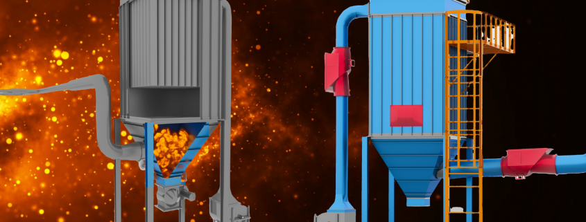
An explosion typically begins when an ignition source enters the dust collector. This ignition source can come from many things and in most cases is never identified. When a pulse cleaning event occurs, a suspended cloud of combustible dust is present in high concentration within the collector. This completes the five elements of a dust explosion and initiates the explosion.

Many dust explosions that occur in process plants are relatively small, leading to limited damage. However, under the right circumstances, even small explosions can escalate into major incidents. This is most commonly the case when secondary dust explosions happen. The typical scenario is that a small “primary explosion” raises a dust cloud, often from dust deposited over time on plant surfaces, and ignites the resulting dust cloud. This “secondary explosion” takes place where often people are present, placing them in immediate danger. Secondary dust explosions can form a chain reaction that can run through a facility as long as fuel is present, leading to injuries and damage to property. 

Mechanism of dust explosions

dust stream with particles of different sizes

Even materials that are traditionally thought of as non-flammable, such as aluminum, or slow burning, such as wood, can produce a powerful explosion when finely divided, and can be ignited by even a small spark

Dusts have a very large surface area compared to their mass. Since burning can only occur at the surface of a solid or liquid, where it can react with oxygen, this causes dusts to be much more flammable than bulk materials. For example, a 1 kg sphere of a material with a density of 1g/cm3 would be about 27 cm across and have a surface area of 0.3 m2. However, if it was broken up into spherical dust particles 50µm in diameter (about the size of flour particles) it would have a surface area of 60 m². This greatly increased surface area allows the material to burn much faster, and the extremely small mass of each particle allows it to catch on fire with much less energy than the bulk material, as there is no heat loss to conduction within the material. When this mixture of fuel and air is ignited, especially in a confined space such as a warehouse or silo, a significant increase in pressure is created, often more than sufficient to demolish the structure.

Even materials that are traditionally thought of as non-flammable, such as aluminum, or slow burning, such as wood, can produce a powerful explosion when finely divided, and can be ignited by even a small spark.

Explosive Materials & Equipment

The following materials are prone to dust explosions:
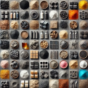
The following materials are prone to dust explosions: • Coal • Fertilizer • Cosmetics • Pesticides • Plastic & plastic resins • Wood • Charcoal • Detergents • Foodstuffs (sugar, flour, milk powder, etc.) • Ore dusts • Metal dusts • Graphite • Dry industrial chemicals • Pigments • Cellulose

Materials that are prone to dust explosions

— Coal

• — Fertilizer
• — Cosmetics
• — Pesticides
• — Plastic & plastic resins
• — Wood
• — Charcoal
• — Detergents
• — Foodstuffs (sugar, flour, milk powder, etc.)
• — Ore dusts
• — Metal dusts
• — Graphite
• — Dry industrial chemicals
• — Pigments
• — Cellulose


Typical industrial equipment that requires explosion protection.
• — Dust Collectors
• — Dryers
• — Cyclones
• — Crushers
• — Grinders
• — Silos
• — Pulverisers
• — Conveyors
• — Conveyor ducts
• — Screw conveyors
• — Bucket Elevators
• — Furnaces
• — Hoppers
• — Bins

Dust Collection Systems to Control Combustible Dust Hazards

A properly designed, operated and maintained dust collection system is the great defense against combustible dust hazards in your facility.

Un sistema de colección de polvo correctamente diseñado, operado y mantenido es la mejor defensa contra los riesgos del polvo combustible en tu planta.

Many process requirements may make elimination of combustible dust, mist, or fume impractical. However, it may still be very possible to manage the dispersion of dust within your plant by using an appropriate and effective industrial ventilation system including dust collection. A well designed, maintained, and operated industrial ventilation system including good hoods, proper duct sizes, and properly selected collection equipment can provide effective dust control and can therefore help manage the presence of dispersed dust. This not only reduces housekeeping frequency and expense, but could also help you reduce the risk of dust explosions in your facility, particularly the destructive secondary explosions, by helping reduce the presence of dispersed fuel in your facility. A properly designed, operated and maintained dust collection system is the great defense against combustible dust hazards in your facility.

Who Sets Standards for Combustible Dust Safety?

The three key entities involved in combustible dust issues: OSHA, NFPA and AHJ

The three key entities involved in combustible dust issues are OSHA, NFPA and AHJ

In general there are three key entities involved in combustible dust issues, each with its own particular area of responsibility: (1) The National Fire Protection Agency (NFPA), (2) OSHA and your (3) local Authority Having Jurisdiction (AHJ). In addition to these agencies, others such as the US Chemical Safety Board (CSB) may assist with investigation of combustible dust accidents and advise on the setting of standards for specific industries.

Combustible Dust Control Strategies

Combating combustible dust hazards effectively in your facility requires dedication and a comprehensive approach. In the following section we will discuss several common combustible dust explosion prevention and protection strategies and technologies as they relate to dust collection systems.

Dust Hazard Analysis Required

NFPA regulations require that a Dust Hazard Analysis (DHA) be performed for all operations that generate, process, handle or store combustible dusts or particulate solids. The standard specifies that the facility owner or operator is responsible for determining if the handled materials are combustible or explosive, and if so, characterizing their properties for the DHA.

NFPA regulations require that a Dust Hazard Analysis (DHA) be performed for all operations that generate, process, handle or store combustible dusts or particulate solids.

NFPA regulations require that a Dust Hazard Analysis (DHA) be performed for all operations that generate, process, handle or store combustible dusts or particulate solids

Hazards associated with combustible dusts and dust collection systems include the following:

  • ● Explosion hazards in the right concentrations and conditions.
  • ● Ignition sources such as open flames, electrostatic discharge, lift truck activity, moving chains, hot surfaces, and rotating equipment with bearings can ignite accumulated or airborne dust, causing a deflagration.
  • ● Downstream through a dust collector’s ducting if not isolated, posing fire, pressure-wave, and noxious-gas hazards.
  • ● Dust buildup on floors, elevated surfaces, and in hidden areas can be disturbed by a primary explosion, become airborne, and contribute to a secondary explosion.
  • ● Dust buildup inside ducting due to deficient filter performance or poor design can contribute to flame or pressure propagation through the duct and into the workspace.
  • ● Metal dusts can have high rates of pressure rise and pressure maximums during a deflagration, causing an improperly designed dust collector to explode and produce shrapnel. • Metal dusts can be reactive with other dust oxides and liquids such as water and produce explosive gases that are highly ignitable.
  • ● Metal dust fires are more difficult to extinguish and can be worsened with the use of improper extinguishing agents.

Explosion Protection and Prevention Technologies

There are many types of devices and systems used to comply with NFPA standards for the explosion protection of dust collection systems, but they fall into two general categories: Passive systems react to the event, while active systems detect and react prior to or during the event.

The goal of a passive system (also called protection) is to control a fire or an explosion so as to keep employees safe and minimize equipment damage in the plant. An active system (also called prevention), by contrast, can prevent an explosion from occurring. An active system involves much more costly technology and may require periodic recertification.

Passive Devices (Protection)

  • ● Explosion venting: Designed to be the “weak” link of the dust collector vessel, an explosion vent opens when predetermined pressures are reached inside the collector, allowing the excess pressure and flame front to exit to a safe area. It is designed to minimize damage to the collector and prevent it from blowing up in the event of a deflagration, thereby reducing the safety hazard. In addition, a flameless vent extinguishes the flame front exiting the vented area, not allowing it to exit the device. This allows conventional venting to be accomplished indoors where it could otherwise endanger personnel and/ or ignite secondary explosions.
  • ● Passive float valve: Designed to be installed in the outlet ducting of a dust collection system, this valve utilizes a mechanical barrier to isolate pressure and flame fronts caused by the explosion from propagating further through the ducting. The mechanical barrier reacts within milliseconds and is closed by the pressure of the explosion.
  • ● Back draft damper: A mechanical back draft damper is positioned in the inlet ducting. It utilizes a mechanical barrier that is held open by the process air and is slammed shut by the pressure forces of the explosion. When closed, this barrier isolates pressure and flame fronts from being able to propagate further up the process stream.
  • ● Flame front diverters: These devices divert the flame front to the atmosphere and away from the downstream piping. Typically, these devices are used between two different vessels equipped with their own explosion protection systems. The flame front diverter is used to eliminate “flame jet ignition” between the two vessels that could overpower the protection systems installed. 

Explosion Dust Collector
inlet options for dust collector

Active Devices (Prevention)

  • ● Chemical isolation: Designed to react within milliseconds of detecting an explosion, a chemical suppression system can be installed in either inlet and/or outlet ducting. Typical components include explosion pressure detector(s), flame detector, and a control panel. This system creates a chemical barrier that suppresses the explosion within the ducting and reduces the propagation of flame through the ducting and minimizes pressure increase within connected process equipment.
  • ● Chemical suppression: Whereas chemical isolation is used to detect and suppress explosions within the ducting, chemical suppression protects the dust collector itself. It is often used, together with isolation, when it is not possible to safely vent an explosion or where the dust is harmful or toxic. The system detects an explosion hazard within milliseconds and releases a chemical agent to extinguish the flame before an explosion can occur.
  • ● Fast acting valve: Designed to close within milliseconds of detecting an explosion, the valve installs in either inlet and/or outlet ducting. It creates a mechanical barrier within the ducting that effectively isolates pressure and flame fronts from either direction, preventing them from propagating further through the process.
  • ● High-speed abort gate: The gate is installed in the inlet and /or outlet ducting of a dust collection system and is used to divert possible ignition hazards from entering the collector, preventing a possible explosion from occurring and preventing flame and burning debris from entering the facility through the return air system. A mechanical barrier diverts process air to a safe location. Abort gates are activated by a spark detection system located far enough upstream to allow time for the gate to activate.

Additional Prevention Devices and Strategies

  • ● Maintain air velocity safety above the minimum conveying velocity: One of the most common sources of potential fuel for combustible dusts is found in the dust collector ductwork. Accumulated dust in ductwork often provides the fuel for devastating secondary explosions or fires. Maintaining the air speed inside the duct safety above the minimum conveying velocity will prevent material buildup.
  • ● Spark arrestor: A mechanical device designed to extinguish spark and embers. They are installed in the ductwork on the inlet side of the dust collector (the dirty air line coming into the unit) upstream from the last pickup but downstream of the collector.
  • A few variations exist, but the device causes the embers to burn out by a combination of the following: Turning vanes that cause the dust-laden air to change direction rapidly and forcing it to take a tortuous path that allows more time for the spark to burn out; screens that break up the ember into smaller pieces that then burn out; a housing larger than the ductwork to reduce the air velocity causing particles large enough to burn to fall out of the airstream; forcing the dust-laden air to impact a flat surface, causing the larger particles to fall out. For proper functioning of the spark trap, the length of duct between the spark source and the spark trap should be at least one duct diameter, and between the spark trap and the dust collector should be at least ten times the duct diameter. A shorter distance will prevent the spark trap from working correctly and is not recommended. Finally, be careful not to confuse a knockout box like device or a cyclone dust collector with a spark arrestor. These devices cannot guarantee 100% spark removal.
  • ● Special Filter Media: While there is no such thing as a “Fire proof filter” certain filter medias provide a level of added resistance to sparks and embers such as flame retardant coatings. Others use conductive materials within the fabric and can assist with static dissipation.
  • ● Sprinklers: Per local building codes you may be required to install traditional water sprinklers inside certain parts of the process, including inside the dust collector incase of fire.
  • ● Choice of filter style: For applications with high dust loading, heavy dusts or “sticky” dusts the use of cartridges may create an additional hazard. With horizontally-mounted cartridges, dust becomes trapped in the pleats in the upper third of the filters This trapped dust can burn even if the filter media is fire retardant.
  • ● Hopper discharge devices: Normally the choice of a discharge varies depending on the process needs and budgetary concerns. With combustible dust applications however the choice of a discharge device can have a major impact on safe operation. Rotary airlocks rated for combustible dust applications work best. Rotary valves enable quick and continuous emptying of the hopper, eliminating the potential for material in the hopper to serve as fuel for a potential explosion or fire. Discharge to a seal drum or hopper can also work well if they are rated to withstand potential explosion pressures. But these must be constantly replaced in order to prevent material backing up into the hopper. Finally, double dump valves rated for combustible dust applications can prove useful in applications with combustible dust but also larger pieces that could potentially jam rotary valves.


So, now that we have seen more clearly what are the hazards you might face and the pasive and active approaches to make your facility safer… its time to make an honest review of what needs to be adjusted in order to minimize risks.

Applications Across Industries for filters p84: cement, waste incineration, power generation, metallurgic and metal processing, and asphalt production

Known for their exceptional durability and high-performance filtration properties, P84 filters are designed to work on extreme conditions across industries like cement, incineration, power generation, and more. Let’s understand why P84 filters are a preferred option for many industrial processes and how they deliver consistent, cost-effective results.

Unique Characteristics of P84 Filters

P84 fibers are needled into high-quality felts, suitable for pulse jet baghouses, and can also be blended with other fibers like PTFE, PPS, PAN, and PES to meet specific operational requirements. P84 filters are engineered with tri-lobal fibers that offer:

p84 fabric close up

  • — High surface area: The irregular shape creates 30–90% more surface area compared to round or oval fibers, enhancing dust collection and cake release.
  • — Temperature resilience: Continuous operation up to 500°F, with short-term peaks of 500°F without fabric degradation.
  • — Chemical resistance: Effective against acids, alkalines, and hydrolysis, making them suitable for aggressive environments.
  • — Non-flammability

Applications Across Industries

P84 filters have become a go-to choice for numerous industries, thanks to their versatility and reliability in extreme conditions:

  • Waste Incineration and Recycling⦿ Waste Incineration Facilities: Handles aggressive chemical environments during scrubber or cooling system downtimes.Supports dust cake formation, capturing fine particles and dioxins, neutralizing acidic flue gases using lime powder and retaining heavy metals with activated carbon. Enables cost-effective bag disposal through incineration, avoiding hazardous waste treatment fees.
  • dust collection in the energy and power generation application⦿ Power Generation: Performs well in coal-fired boilers, resistant to SO₂ and oxygen. Suitable for biomass-fired plants with varying operating loads and flue gas compositions. Operates efficiently in wet scrubbing systems and semi-dry absorption setups.


Advantages of P84 Filters

  1. Low Maintenance Costs: Long service life minimizes bag replacements. Durable needle felts withstand cleaning pressures up to 6 bar without delamination.
  2. Cost-Effective Design: Standard cages are sufficient; no need for costly double-wire cages. Lower energy consumption due to reduced pressure drops and efficient cleaning cycles.
  3. Environmental Safety: Minimal toxic emissions during incineration of used bags. Meets stringent emission standards, ensuring regulatory compliance.
  4. High Flexibility: Performs across a wide range of flue gas compositions, temperatures, and dust loads. Adapts to varying operating conditions in industries using secondary fuels.

Operational Guidelines for Filters P84

Temperature Management 

In general, the life cycle of any synthetic material is reduced with rising temperatures. Every 50° F the speed of the chemical reaction doubles! This increase is lower for P84 but in principle also valid for P84. Therefore the continuous operating temperature in conjunction with the flue gas parameters has a decisive influence on the lifetime of filter bags. Special attention has to be taken into consideration in case of the occurrence of high operating temperatures together with oxidizing agents like O2 and NO2. Most of all NO2 is very aggressive for any kind of synthetic fiber, while NO has no influence on the life cycle at all.

Continuous operation should stay within the recommended temperature range to maximize lifespan:

  • 235°–320°F: 60–72 months
  • 320°–355°F: 24–48 months
  • 355°–392°F: 12–36 months

Short term peaks of 500° F do not cause problems for P84, however longer periods around 500 °F may lead to fabric shrinkage in case the heat treatment of the needle felt in production has not been made in a proper way. Short-term peaks are defined with duration of the app. from 5 to 10 minutes. Depending on the continuous operation temperature and other flue gas components, the total peak temperature duration can be limited from 100 to app. 400 hours per year for achieving the requested bag life.

Moisture and Dew Point

Operation at or below the acid –and water– dew point should be avoided at any time. Heating baghouses during shutdowns can mitigate moisture-related risks.

Condensation as well as operation close to the dew point may result in problems in case the pH of the dust is extremely acidic (pH < 3) or alkaline (pH > 11). In that case, heating of the bag house during shutdowns is recommended. As long as moisture is excluded, dry acidic or dry alkaline dust does not attack the fiber. High moisture contents (> 35 % vol) have to be taken into consideration as well.

Bag Disposal at the End of Filter Life

In comparison with PTFE materials or glass products, P84 shows very low toxic gas generation when being burnt. Instead of expensive bag disposal at hazardous waste treatment plants, P84 bags can be burnt in the incinerators of end users.

Conclusión

P84, PPS and other similar fabrics are used in high temp applications to replace aramid or fiberglass when certain chemical or extra high moisture contents make aramid ineffective.

Los tejidos P84 se utilizan en aplicaciones de alta temperatura

If you’re considering upgrading your dust collection system or need help selecting the right filter for your specific application, reach out to us. It is always better to double check with a dust collection expert before making the change to a different filter fabric.  

System operators and maintenance technicians must keep a close watch on the differential pressure at all times to ensure proper operation of the system.
Powder & Bulk Solids Magazine Cover

Portada de la revista Powder & Bulk Solids

Este artículo fue publicado por baghouse.com en la edición de enero de 2025 de la revista Revista Powder Bulk & Solids. También puedes leerlo en este enlace:

Cómo Mantener y Operar Colectores de Polvo Usando la Presión Diferencial

Baghouse.com personnel monitoring the differential pressure in a cartridge collector

Monitorear regularmente la presión diferencial nos dará información sobre cómo está operando nuestro sistema.

La presión diferencial es el dato clave que se utiliza para determinar cómo está funcionando un colector de polvo. Monitorear esta variable es como revisar la presión arterial en el cuerpo humano. Así como la presión arterial indica la salud y eficiencia del sistema circulatorio, la presión diferencial ofrece una medición vital de qué tan bien está funcionando el colector de polvo.

Los operadores del sistema y los técnicos de mantenimiento deben vigilar de cerca la presión diferencial en todo momento para garantizar el correcto funcionamiento del sistema. También deben monitorearla para planificar el mantenimiento y realizar cualquier modificación al sistema, como aumentar la capacidad o mejorar la eficiencia.

Lo que la presión diferencial nos dice...

...Sobre los filtros de su colector de polvo


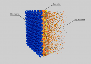
dust cake in a dust collector filter

Los filtros obstruidos por largo tiempo con una gran capa de polvo tendrán un mayor nivel de fugas.

● Si la presión diferencial es alta

  • ○ Una presión diferencial consistentemente alta es una señal de que los filtros están obstruidos (es decir, el tejido está completamente saturado de partículas de polvo). Una vez obstruidos, los filtros ya no pueden ser limpiados y deben ser reemplazados.
  • ○ Los filtros obstruidos o incluso los filtros con una gran acumulación temporal de polvo tendrán mayores emisiones (es decir, fugas). Verifique los niveles de emisiones con medidores de opacidad o detectores de filtros rotos .
  • Una relación aire-tejido insuficiente para la aplicación resultará en bolsas sobrecargadas de polvo y el sistema de limpieza no podrá limpiar las bolsas de manera efectiva.

● Si la presión diferencial es baja

  • ○ Una presión diferencial anormalmente baja (por debajo de 3″) puede ser señal de agujeros, desgarros o costuras sueltas en las bolsas o de que los filtros no están instalados correctamente (banda de sujeción desalineada en modelos de carga superior, abrazaderas de bolsa sueltas en unidades de carga inferior).


…Sobre su sistema de limpieza


blinded pleated filters

Una limpieza deficiente de las bolsas resultará en mayor presión diferencial (DP), ya que la capa de polvo se acumulará más rápido de lo que se puede limpiar

● Si la presión diferencial es alta

  • ○ Una limpieza inadecuada de las bolsas resultará en una presión diferencial más alta, ya que el polvo se acumulará más rápido de lo que se puede limpiar.
  • ○ En un colector de polvo que usa pulso de aire comprimido, esto puede ser causado por baja presión de aire comprimido, aire contaminado (suciedad, agua o aceite en el reservorio de aire), tubos de soplado mal alineados o venturis de jaula mal alineados o faltantes.
  • ○ Si los ciclos de limpieza (es decir, los pulsos de aire) no están configurados correctamente, las bolsas no se limpiarán adecuadamente. (“On Time” es el tiempo durante el cual la válvula de aire comprimido está abierta. Si está configurada con demasiado tiempo de apertura, el estallido de aire será demasiado débil para limpiar la bolsa. Si está configurado con poco tiempo de apertura, no liberará suficiente aire para limpiar toda la longitud de la bolsa).
  • ○ El orden en que se limpian las bolsas (llamado “secuencia de disparo”) debe estar escalonado (1, 4, 2, 5, 3, 6) para que las filas sucesivas no se limpien una tras otra (por ejemplo, 1, 2, 3, 4, 5, 6).


● Si la presión diferencial es baja

  • Holes in a dust collector filter bag

    Trabajar con un excesivo aire comprimido causará un fallo prematuro de las bolsas, a menudo creando problemas de abrasión o incluso provocando agujeros en el material

    ○ La limpieza excesiva de las bolsas provocará un desgaste innecesario de los filtros y llevará a fallos prematuros.
  • ○ Si la presión del aire comprimido es demasiado alta limpiará mejor los filtros, también causará un fallo prematuro del filtro, creando a menudo problemas de abrasión o incluso agujeros en el tejido.
  • ○ Dado que las emisiones son más altas cuando se pulsan los filtros, un exceso de pulsos lleva a un aumento de las emisiones.


…Sobre problemas con su sistema de recolección de polvo

● Si la presión diferencial es alta

  • ○ Los cambios repentinos en la presión diferencial pueden ser causados por condiciones inesperadas o cambios en el proceso que el sistema está ventilando. Cualquier problema en el colector de polvo podría ser señal de que algo potencialmente más serio está ocurriendo más arriba del equipo.
  • ○ Una presión diferencial consistentemente alta podría ser señal de que el sistema está subdimensionado y no puede soportar la carga que se le está colocando.
  • ○ Las placas deflectoras desgastadas, las cajas de caída y un diseño de flujo de aire deficiente conducen a la sobrecarga de los filtros y a una presión diferencial alta.
  • ○ Una acumulación excesiva de polvo en la tolva puede llevar a la reentrada de polvo y sobrecargar los filtros.
  • ○ El polvo húmedo o pegajoso, que es difícil de limpiar, puede ser señal de fugas cerca de las compuertas o grietas en la estructura del baghouse que permiten que entre humedad o aire frío, causando condensación en los filtros.

● Si la presión diferencial es baja

  • ○ Las grietas o agujeros en la estructura o en la placa tubular del colector de polvo pueden causar una reducción significativa en la presión diferencial y llevar a un gran aumento de las emisiones.

¡Cuidado con las mediciones incorrectas!

Magnehelic pressure gauge

Si los operadores tienen lecturas incorrectas, podría resultar en daños al sistema, un aumento de las emisiones o incluso en riesgos de incendio y polvo combustible

Si los operadores tienen lecturas incorrectas, esto podría resultar en daños al sistema, aumento de emisiones o incluso riesgos de incendio y polvo combustible. Como se mencionó en artículos anteriores, es vital asegurarse de que las lecturas de la presión diferencial provenientes de la unidad sean precisas.Para ello, es mejor hacer del mantenimiento de las líneas de aire, manómetros y controladores una parte regular del programa de mantenimiento preventivo del colector de polvo.

How to Reduce Maintenance on a Dust Collection Controller?

To reduce maintenance on a dust collection controller, upgrade the system to an on-demand (differential pressure) cleaning cycle, use dry, oil-free compressed air, and set staggered pulsing sequences. These practices prevent over-cleaning, reduce wear on diaphragm valves, and maximize filter lifespan.

Key Strategies to Minimize Controller Upkeep

  • ⦿ Switch to On-Demand Cleaning: Avoid continuous, timed pulsing, which wastes compressed air and causes premature wear on controller relays, solenoid valves, and filter bags. Instead, connect the controller to a Differential Pressure (dP) sensor. The controller will only trigger a cleaning cycle when the filters are actually loaded with dust.
  • ⦿ Install Air Dryers and Filters: Contaminants like water or compressor oil in your pneumatic lines are the leading causes of solenoid and diaphragm valve failures. Ensure your system is equipped with an adequate compressed air dryer and inline coalescing filters.
  • ⦿ Stagger the Pulse Sequence: Do not pulse rows sequentially (e.g., Row 1, then Row 2, then Row 3). This allows dust released from one row to immediately settle on the adjacent, freshly cleaned row. Program your controller to stagger or skip rows to allow dust to drop directly into the hopper.
  • ⦿ Optimize Pulse Width and Interval: Check the manufacturer’s manual for your specific media. A typical pulse width should be roughly 0.05 to 0.15 seconds. Decreasing the frequency of your pulses and increasing the “off-time” between pulses saves compressed air and reduces mechanical strain on the valves.
  • ⦿ Regular Diagnostic Audits: Test your solenoids periodically by listening for a crisp “poof” sound at each valve. Replace cracked diaphragms or sticking solenoids immediately, as one failing valve can compromise the performance of the entire cleaning cycle.

Conclusión

¿Cuántas decisiones de mantenimiento y operación relacionadas con su colector de polvo o baghouse están influenciadas por la presión diferencial? 

¡Todas!


¿Tiene preguntas sobre la presión diferencial? ¿Tiene lecturas extrañas y no está seguro de qué significan? ¡Por favor, llámenos o envíenos un correo a info@baghouse.com y permítanos ver cómo podemos ayudarle!

Cosmetics Group USA is a California-based maker of a range of beauty products, partnering with the world's most well-known cosmetics brands.

A Dust Collection Success Story at Cosmetics Group USA

Antecedentes

Cosmetic Group USA is an ever growing developer and manufacturer of cosmetics and skin care for national and international brands.

Cosmetic Group USA is an ever growing developer and manufacturer of cosmetics and skin care for national and international brands.

Cosmetics Group USA is a California-based maker of a range of beauty products, partnering with the world’s most well-known cosmetics brands. The process of cosmetics manufacturing begins with the careful blending of raw materials to create the desired formulations. These powders are then finely milled and sifted to achieve the right texture and consistency.

Alcance del proyecto

As part of their plans to expand and upgrade their Los Angeles factory, Cosmetics Group leadership recognized two main issues with dust collection that needed to be addressed:

  1. An efficient, central dust collection system with capacity to support planned operations and expansion in the factory.
  2. The air pressure in the building required balancing, as the dust collection system generated significant negative pressure, resulting in slamming doors, potential dust and particulates being pulled into the building through windows and doors, and inefficient heating and cooling of the facility.

Solución

To resolve these challenges, the company partnered with Baghouse.com to design and install a dust collection system that would satisfy their unique challenges.

“Our team worked efficiently to ensure the new dust collection system was up and running ahead of schedule, minimizing any disruptions to the Cosmetics Group’s operations" said David Dal Santo, Systems Engineer for this project. 


Baghouse.com developed a dust collection system using two 4-32 cartridge dust collectors with high-efficiency nano-media cartridge filters and twin 75 HP ground-mount fans. The various process dust pickup points in the lab and production areas were connected to the dust collectors via galvanized steel, clamp-together duct, an economical duct configuration that is perfect for lighter duty applications like cosmetic powder and dust.

“With high-efficiency nano-media cartridge filters and a robust ductwork design, we’re confident that this setup will exceed expectations for years to come” said David Dal Santo.

Positioned on the clean air side of the unit, the HEPA after-filter acts as a secondary filtration stage, capturing even the tiniest microscopic particles before the air is returned to the facility.

Positioned on the clean air side of the unit, the HEPA after-filter acts as a secondary filtration stage, capturing even the tiniest microscopic particles before the air is returned to the facility.

To address the pressure balancing challenge, Baghouse.com designed the dust collection system exhaust to return to the building. Dual HEPA after-filter units were installed on the return air ductwork to meet compliance requirements and ensure the highest filtration efficiency for the filtered air that would be returned to the building. Baghouse.com also supplied and installed a central vacuum system with 30+ vacuum ports with flap valves for easy plug in of hoses where necessary.

In addition to the dust collection system sizing design, and delivery of the equipment, a Baghouse.com team installed the dust collection system and commissioned the units, successfully completing the project.

Conclusión

Baghouse.com developed a dust collection system using two 4-32 cartridge dust collectors with high-efficiency nano-media cartridge filters and twin 75 HP ground-mount fans. The various process dust pickup points in the lab and production areas were connected to the dust collectors via galvanized steel, clamp-together duct, an economical duct configuration that is perfect for lighter duty applications like cosmetic powder and dust.

Newly installed cartridge collectors, ductwork and HEPA After-Filters

“We were excited to take on this challenge and are thrilled with the outcome. Helping Cosmetics Group USA expand their operations while solving their dust collection issues was truly a rewarding experience” said Matthew Coughlin,, Engineer and Owner of Baghouse.com. 


Happy with the results of their new dust collection system, Cosmetics Group USA continues to work with Baghouse.com to support additional future expansion plans for their factory.

In addition to the points we mentioned in our article How to Avoid Undersizing a Baghouse Dust Collection System, here are a few additional methods to help ensure you get the right system for your operation.

In addition to the points we mentioned in our article How to Avoid Undersizing a Baghouse Dust Collection System, here are a few additional methods to help ensure you get the right system for your operation:

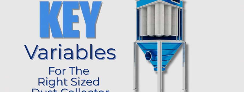
Baghouse variables such as air-to-cloth ratio, power consumption, fan capacity, installation footprint, bag material, cleaning cycle type, required bag life, etc., need to be considered when designing the system.

Baghouse variables such as air-to-cloth ratio, power consumption, fan capacity, installation footprint, bag material, cleaning cycle type, required bag life, etc., need to be considered when designing the system

1. Set Technical Standards

On medium to large jobs (say $1 million+), pay an A/E, or a trusted baghouse consultant, to write a spec setting minimum technical standards for air-to-cloth ratio, power consumption, fan capacity, installation footprint, bag material, cleaning cycle type, required bag life, etc., and spelling out exactly what NFPA/OSHA performance standards will have to be met. The installed equipment will actually have to pass a field test before the vendor gets the last 10% of his fee, or a performance bond will have to be posted by the vendor. This type of detailed spec will scare off 90% of the “corner cutters.” Then, pay a testing company to actually do the test.


2.  Verify Vendor Experience

Customer References List 2024 for Baghouse.com

For smaller, low-cost projects, you can still ask each vendor for a contact list of their past customers who have installed their equipment for applications similar to yours in the last 3 to 5 years. 

Again, this will eliminate any vendors who lack experience with your type of problem or who enjoy shafting their customers. Then, actually make the phone calls and talk to the plant engineer responsible for keeping the unit operating. You will be amazed at how much information you can get for free from both happy and unhappy past customers.

"The vendor assured us that the system would handle our needs, but it was undersized from the beggining. We’re constantly replacing filters and dealing with high-pressure drops. In hindsight, I realize we should have consulted a dust collection expert before making the purchase."

3. Compare Multiple Vendors

Maintenance Manager contacting different vendors asking for ballpark quotes for their dust collection system

Instead of just contacting two or three vendors with your in-house preliminary spec, contact five or six, and ask for quick, ballpark, budgetary quotes. Within a few weeks, you will know which vendors are unrealistically below (or too high above) the “pack” to further bother with. Do this for 2 or 3 projects and you should get an excellent idea of which one or two vendors in your area are a trustworthy, economical fit for your operation, and you can just use them in the future.


3D design of a dust collector and the ductwork

4. Plan for Future Growth

When specifying your dust collection system, always consider your plant’s potential for future expansion. Systems that are undersized today will be even more problematic if your operations scale up. It’s a good idea to leave some room for increased airflow or additional filter capacity if your facility is expected to grow in the coming years.

By following these steps, you can significantly reduce the risk of ending up with an undersized dust collection system that costs you more in the long run due to operational inefficiencies, fines from non-compliance, and higher maintenance costs.