How Can I Buy My Dust Collector Filters Cheaper?
When the time comes to replace your worn-out baghouse filters, what do you normally do?

Certain filter OEMs make people believe they are locked into a proprietary filter design that only they can supply and that without this one piece, their system won’t work efficiently
Do you just call up the original baghouse system manufacturer or sales rep that supplied you with it armed with a filter part number or gibberish product codes and then wait just to get a sky-high price?
Certain manufacturers deliberately sell their units cheaper and then make people think they are locked into a proprietary filter design that only they can supply, and thus, they charge outrageously high prices for them.
This is common with many cartridge collector OEMs, whereby they win the initial unit sale by undercutting other manufacturers and then plan on making their profit on the expensive replacement filters later on. This marketing technique is commonly called the “razor blade” system, for its well-known use by makers of disposable razors and cartridges.
At that moment, you may wonder, “Can I buy my dust collector filters cheaper?” Well, the simple answer is YES!
Here at Baghouse.com, we offer replacement filters, cartridges, and pleated filters for all makes and models of dust collectors, including the most popular brands, such as Farr, Donaldson/Torrit, and more. Our prices often come in significantly cheaper than buying directly from the original dust collector manufacturer, sometimes as much as 50% less!
Read the related article: Why Are Some Baghouse Filters More Expensive Than Others?

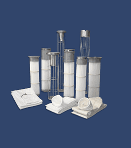
Baghouse.com filters are manufactured to meet the highest quality standards
By going directly to a filter manufacturer like Baghouse.com, you can reduce your spending on dust collector filters by 20% – 50% compared to purchasing them through your system supplier. Baghouse.com filters are manufactured to meet the highest quality standards and can be found in thousands of facilities across North America in some of the toughest applications.
Additional info: How To Get The Best Price For Baghouse Filters?