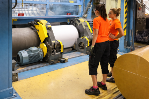
Questions & Answers About IoT Sensors and Remote Monitoring
This article distills five expert questions from the Boosting ROI with Smart Sensors & Industrial IoT Webinar, featuring Eric Schummer – CEO of Senzary and Matt Coughlin, Engineer and Owner of Baghouse.com, into practical guidance for bringing this technology to your dust collection systems.
— "Are there software tools for predicting possible failures in IoT networks?"
Yes. There are software tools for predicting maintenance and failures, and this is a major driver for many customers. Tools address different equipment types—vibratory, rotational, conveyors, elevators, pumps and motors, kilns, and more—by monitoring a range of signals such as gas concentrations (over 20 gases), inclinations, tilts, vibrations, pressures, and even metal particles in oil.
By analyzing these data points over time, they help reveal how a system degrades, enabling predictive maintenance decisions, whether manual or automated.
— "How do sensors and gateways maintain uptime?"
LoRaWAN is a service-enabled protocol that ensures robust uptime. The system continuously monitors every packet in real time and coordinates between sensors and gateways 24/7, adjusting for distance, noise, quality, and signal conditions. Sensors are designed to save battery life and rejoin the network after disruptions, with transmissions typically under one second due to small payloads.
The platform uses multiple gateways and selects the best one for each transmission. AI tools monitor packet counts, missing packets, and signal degradation to identify issues early, such as a gateway disconnect, supporting proactive maintenance and uptime.
— "How to measure dust and noise in concrete plants?"
Dust sensors measure both particle counts and particle mass, with counts and mass expressed on scales tied to health-relevant metrics. Particle counts may use very fine measurements (down to small PPM-like scales in some contexts, e.g., data centers), while common regulatory references use 2.5 and 10 micrometer equivalents. Particle mass concentration per cubic meter is also tracked, using scattered lasers from compact, portable sensors that can be placed in various locations.
Noise is measured as air-pressure–based sound levels (decibels) for regulatory and worker exposure purposes, and ultrasound ranges (0–80 kHz) can be used to monitor equipment like conveyors and motors for predictive maintenance. The discussion also suggests evaluating the dust collection system’s basics (sizing, hood design, capture velocities) to maximize the effectiveness of IoT sensing.
— "What are the Basics Before IoT Implementation?"
Before IoT deployment you should establish solid dust collection basics. This includes having systems sized appropriately, with proper hood design and capture velocities—the “dust collection 101.”
Once these fundamentals are in place and functioning, IoT sensors and predictive maintenance tools can provide meaningful monitoring and optimization rather than chasing issues after they occur.
— "Can sensors handle heat and dust?"
Yes. The sensors are described as protected electronics with IP67 ratings, meaning they are resistant to water and dust ingress and suitable for harsh environments. The transcript cites real-world examples of sensors operating in extreme conditions, including 400–500 degrees Celsius (or Fahrenheit) in steel industry contexts, demonstrating that these devices can function reliably in hot, dusty industrial settings.
Every facility is different, and the remote monitoring needs of your systems can vary widely depending on your dust, equipment, layout, and production demands.
If you didn’t see your question here—or if you’re dealing with a specific issue in your system—don’t hesitate to reach out. Our team is always available to help you find practical, effective solutions and guide you through any challenges you may be facing.
We’d be glad to answer your questions and support you in improving the safety of your dust collection system.
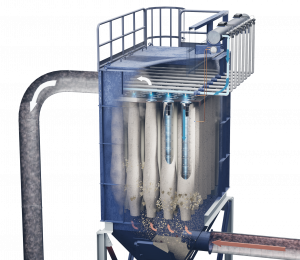
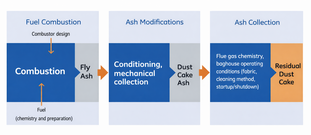
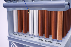
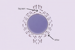
 In pulse-jet baghouses, filtration does not primarily happen within the filter fibers themselves. Instead, the system relies on something called a filter cake.
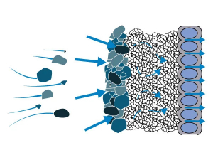

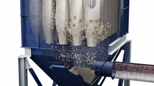
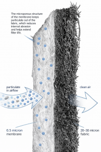 When membrana PTFE is added to the filter media, collection efficiency increases even further.

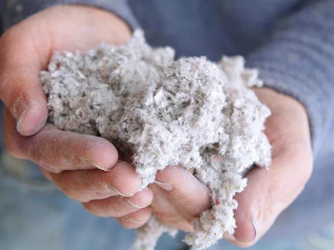 El polvo de papel y empaque es engañosamente ligero. Las fibras de celulosa, el polvo de tissue y las partículas finas de cartón no caen al suelo como lo hacen otros polvos industriales más pesados. Permanecen suspendidos en el aire, se desplazan por toda la planta y se depositan en lugares que los operadores rara vez inspeccionan. Procesos como corte, rebobinado, troquelado, transporte, enfardado y acabado generan partículas finas que se dispersan rápidamente si las velocidades de captación disminuyen aunque sea un poco.

 El polvo de papel y cartón es peligroso porque combina tres problemas al mismo tiempo: es respirable, combustible y altamente volátil. Cuando está suspendido en el aire, incluso concentraciones relativamente bajas pueden encenderse si hay una fuente de ignición presente. Cuando se le permite asentarse, el polvo se acumula rápidamente sobre superficies horizontales, creando combustible para explosiones secundarias. Desde el punto de vista de la salud, la exposición prolongada también contribuye a una mala calidad del aire interior y a problemas respiratorios, particularmente en operaciones de papel tissue y papel fino.
 ¿El control de polvo realmente puede reducir las interrupciones a la producción en plantas de empaque?
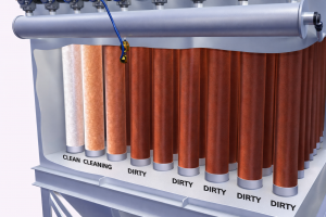


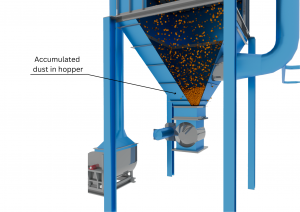
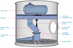
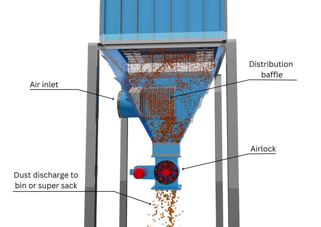 El aire cargado de polvo suele ingresar a través de una entrada de aire sucio ubicada en la tolva, debajo de los filtros. Si esa entrada dirige el flujo de aire hacia abajo o genera turbulencia excesiva, el polvo puede arremolinarse hacia arriba y volver a depositarse en los filtros. El resultado es una carga de polvo mayor de la que los filtros pueden manejar de manera eficiente. Agrandar la entrada para reducir la velocidad o instalar un deflector dentro de la tolva puede mejorar significativamente la distribución del flujo de aire. Estos deflectores suelen ser económicos y fáciles de instalar, y aun así reducen la turbulencia, minimizan la re-entrada de polvo y protegen los filtros contra cargas desiguales y abrasión.